Gantry type truss manipulator

A manipulator and gantry-type technology, applied in the direction of manipulators, program-controlled manipulators, chucks, etc., can solve the problems of unsatisfactory automatic production, inability to guarantee operation stability and precision, and achieve the goal of saving manpower, ensuring stability and improving load capacity Effect

Pending Publication Date: 2019-03-22
德是正(苏州)智能科技有限公司
View PDF7 Cites 7 Cited by
  • Summary
  • Abstract
  • Description
  • Claims
  • Application Information

AI Technical Summary

Problems solved by technology

[0002] The gantry truss is generally composed of a gantry and a front and rear moving mechanism, a lateral movement mechanism and a lifting mechanism arranged on the gantry. The lifting mechanism is equipped with a mechanism for transporting materials. Because the gantry truss has the advantages of large load and easy operation, it is the current factory realization. The main equipment for the automatic handling of heavy materials; while the existing gantry truss generally only has a relatively simple moving mechanism, which cannot guarantee the stability and accuracy of the operation. Meet the needs of automated production

Method used


Image

  • Gantry type truss manipulator
  • Gantry type truss manipulator
  • Gantry type truss manipulator

Examples


Embodiment Construction

[0018] The present invention will be further described in detail below with reference to the accompanying drawings and specific embodiments.

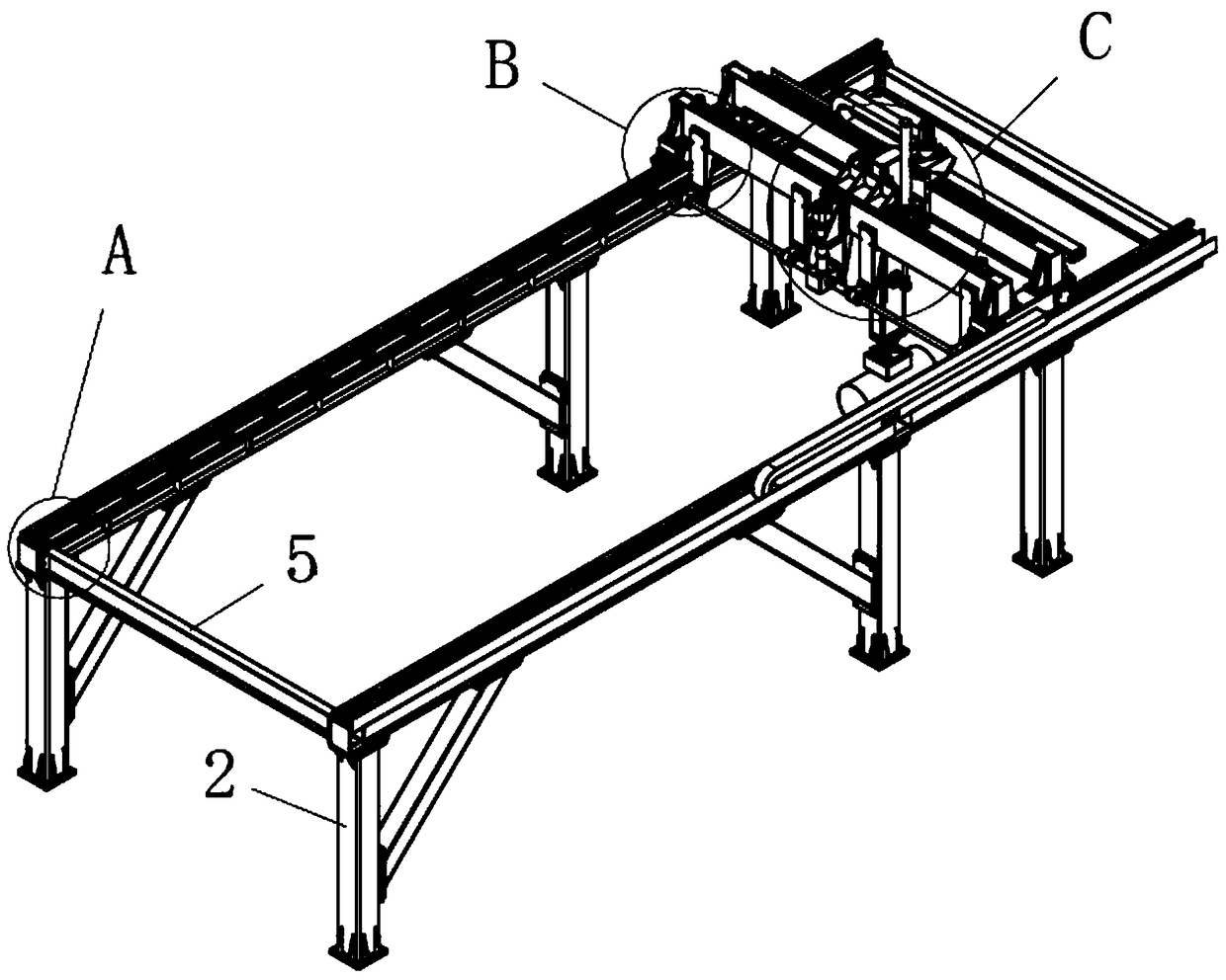
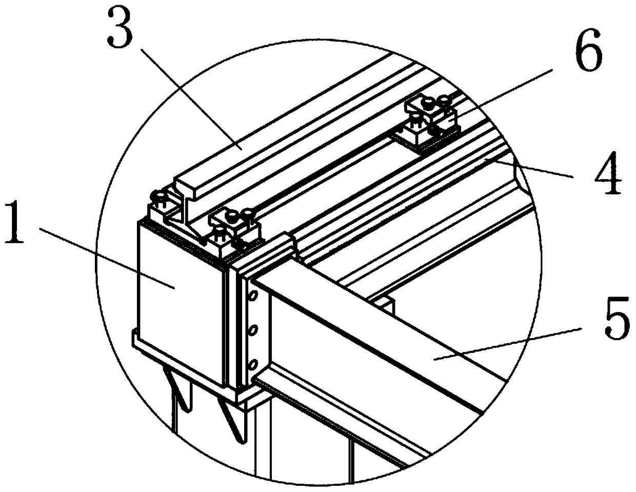
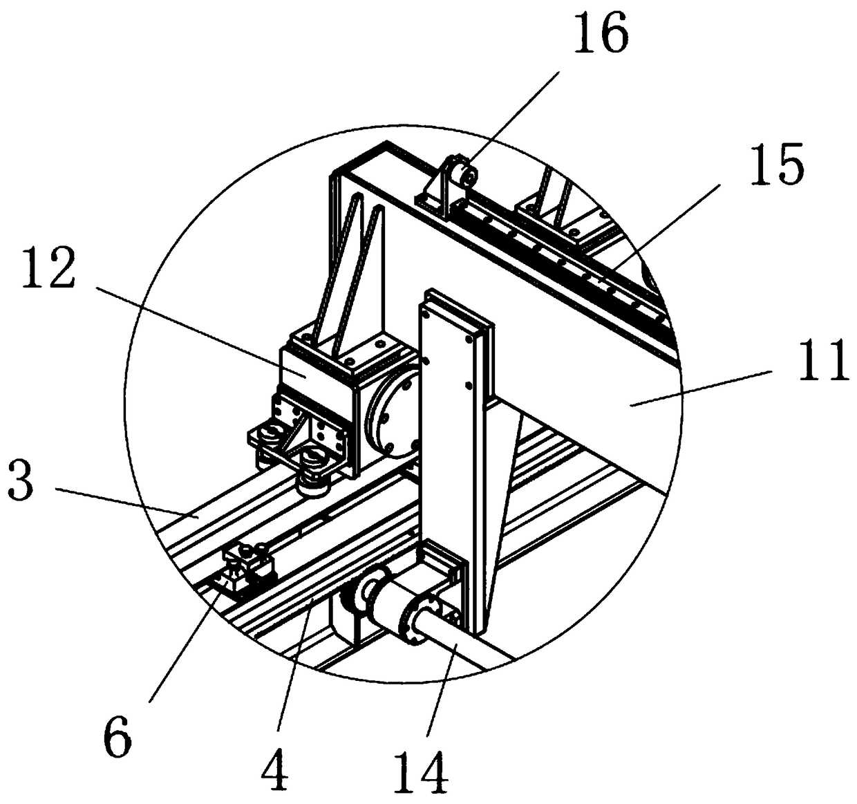
[0019] like Figure 1-5 As shown in the figure, a gantry type truss manipulator according to the present invention includes a gantry support, a forward movement mechanism, a transverse movement mechanism and a manipulator assembly; the gantry support includes two parallel forward movement bearing beams 1, each forward movement The lower side of the bearing beam 1 is provided with a plurality of legs 2, and a reinforcing beam 5 is arranged between the two forward-moving bearing beams 1, and the reinforcing beam 5 is arranged at the front and rear ends of the forward-moving bearing beam 1 to improve the stability of the overall structure. Each forward-moving bearing beam 1 is provided with a forward-moving guide rail 3, a forward-moving rack 4 and a plurality of slide rail pressing seats 6 arranged along the length direction of the forwar...


PUM


Abstract

The invention discloses a gantry type truss manipulator. The gantry type truss manipulator comprises a gantry support, a forward moving mechanism, a transverse moving mechanism and a manipulator assembly. The gantry support comprises forward moving carrying beams. A forward moving guide rail and a forward moving rack are arranged on each forward moving carrying beam. The forward moving mechanism comprises a forward moving frame. Sliding seats, a forward moving gear driving device, a forward moving gear transmission assembly, transverse moving sliding rails and transverse moving racks are arranged on the forward moving frame. The transverse moving mechanism comprises a transverse moving frame. A transverse moving gear driving device, a lifting driving device and a lifting lazy arm are arranged on the transverse moving frame. The manipulator assembly is arranged at the lower end of the lifting lazy arm. A gantry type truss provided by the scheme moves through the structures of gears, theracks and the sliding rails, moving and positioning of the truss are more accurate, automatic operation is achieved through programming, the efficiency is improved, and manpower is saved; meanwhile,the structures of all parts are optimized, the load capacity is increased, and the operation stability is improved; and electric permanent magnets and the gantry truss are combined and can serve as special carrying tools for circular rod shaped materials.

Description

technical field [0001] The invention relates to the technical field of mechanical handling, in particular to a gantry type truss manipulator. Background technique [0002] The gantry truss is generally composed of a gantry and a front and rear moving mechanism, a traversing mechanism and a lifting mechanism arranged on the gantry. The lifting mechanism is provided with a mechanism for handling materials. Because the gantry truss has the advantages of large load and easy operation, it is currently the factory implementation. The main equipment for automatic handling of heavy materials; and the existing gantry truss generally only has a relatively simple moving mechanism, which cannot guarantee the stability and accuracy of operation. Meet the needs of automated production. SUMMARY OF THE INVENTION [0003] The purpose of the present invention is to provide a gantry-type truss manipulator with high efficiency, stable and reliable structure in order to overcome the deficienc...

Claims


Application Information

Patent Timeline
Patent Type & Authority Applications(China)
IPC IPC(8): B25J9/02B25J9/10B25J15/06
CPCB25J9/026B25J9/102B25J15/0608
Inventor 罗贤
Owner 德是正(苏州)智能科技有限公司
Why Eureka
Try Eureka