Cable processing device for optical communication equipment

A processing device and optical communication technology, applied in conductor/cable supply device, cable/conductor manufacturing, circuit, etc., can solve problems such as poor cooling effect and unclear cooling structure, achieve better cooling effect and prolong cooling time , The structure of the device is simple and compact

Inactive Publication Date: 2020-12-01
CHONGQING COLLEGE OF ELECTRONICS ENG
View PDF1 Cites 0 Cited by
  • Summary
  • Abstract
  • Description
  • Claims
  • Application Information

AI Technical Summary

Problems solved by technology

[0004] The cooling structure of the above-mentioned patent is not clear, and the cooling effect is not good, so a device is urgently needed to solve this problem

Method used


Image

  • Cable processing device for optical communication equipment
  • Cable processing device for optical communication equipment
  • Cable processing device for optical communication equipment

Examples


Embodiment 1

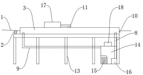
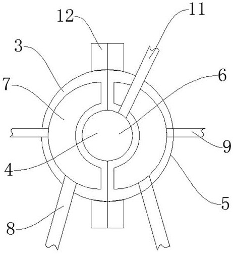
[0038] Such as Figure 1-Figure 8 As shown, a cable processing device for optical communication equipment includes a cable 1, an incoming wire guide wheel 2, a left cooling half-barrel 3 and a left wire-covering tank body 4. The upper part of the incoming wire guide wheel 2 is provided with a cable wire 1, and the cable One side of the line 1 is provided with a left cooling half barrel 3, and the inside of the left cooling half barrel 3 is provided with a left wire-covered tank 4, and the left side of the left wire-covered tank 4 is provided with a right cooling half-barrel 5, and the right cooling half-barrel 5 is provided with a There is a right covered wire groove 6, and the inside of the right cooling half barrel 5 is provided with an internal cold zone pipeline 7, one end of the internal cold zone pipeline 7 is provided with a coolant inlet pipe 8, and the other side of the internal cold zone pipeline 7 is provided with a coolant Outlet pipe 9, a first temperature sensor ...

Embodiment 2

[0040] The difference between this embodiment and Embodiment 1 is that in this embodiment, the cable wire 1 is slidably connected with the wire inlet guide wheel 2, the left wire covering groove body 4 is formed in the left cooling half barrel 3, and the right wire covering groove 6 is formed in the Right inside the cooling half bucket 5. This setting can make the device more stable. Further, the semiconductor cooling chip 25 is fixed on the first mounting base 26 through buckles, and the buckling plays a role of fixing, so that the semiconductor cooling chip 25 is easy to install and disassemble.

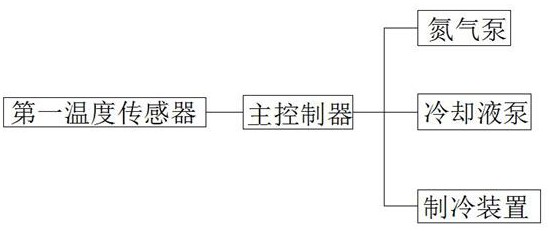
[0041] The specific working principle of the present invention is: when using the device, when working, the cable 1 enters the left covered wire tank 4 in the left cooling half barrel 3 and the right covered wire in the right cooling half barrel 5 through the wire inlet guide wheel 2 In the cylinder formed by the tank 6, the main controller 18 controls the nitrogen pump 17 to turn...


PUM


Abstract

The invention discloses a cable processing device for an optical communication device. The cable processing device comprises a cable line, an incoming guide wheel, a left cooling half barrel and a left wrapping slot body. The cable line is arranged at the upper part of the incoming guide wheel; the left cooling half barrel is arranged at one side of the cable line; and the left wrapping slot bodyis arranged inside the left cooling half barrel. A right cooling half barrel is disposed at one side of the left wrapping slot body; a right wrapping slot is formed in the right cooling half barrel; an internal cold area pipeline is arranged inside the right cooling half barrel; a cooling liquid inlet pipe is arranged at one end of the internal cold area pipeline; and a cooling liquid outlet pipeis arranged at the other side of the internal cold area pipeline. A first temperature sensor is disposed at one end of the left cooling half barrel. The cable processing device has the following beneficial effects: firstly, the device has a simple and compact structure; the cooling time is extended by the long-tube cooling pipeline; and the cable cooling effect is improved by temperature sensing;and secondly, inert gas is added to the device to prevent aging of the cable line, so that the cable quality is guaranteed.

Description

technical field [0001] The invention relates to the technical field of cable processing, in particular to a cable processing device for optical communication equipment. Background technique [0002] The traditional power cable manufacturing industry, due to the influence of traditional production technology and production equipment, often produces unsatisfactory product quality. Such as: cable processing is usually in the air atmosphere, and the cooling water tank is usually used to cool the cable, which is easy to cause the surface oxidation of the cable and affect the service life of the cable. [0003] The Chinese patent with the application number CN201621217571.1 discloses a cable processing device, which includes a pay-off reel, a stranding machine, an electromagnetic induction heating device, a gas cooling device, and a take-up reel. The outlet end enters the wire stranding machine, and then the wire outlet end of the wire stranding machine is heated by the electroma...

Claims


Application Information

Patent Timeline
Patent Type & Authority Patents(China)
IPC IPC(8): H01B13/00
CPCH01B13/0003H01B13/0036
Inventor 刘鹏
Owner CHONGQING COLLEGE OF ELECTRONICS ENG
Why Eureka
Try Eureka