
Display panel driving method

A display panel and driving method technology, applied to static indicators, instruments, etc., can solve problems such as large data compensation range, inability to change non-heavy-loaded screen display, and difficulty in developing non-heavy-loaded screens, and achieve the effect of improving accuracy

Active Publication Date: 2020-08-04
SHENZHEN CHINA STAR OPTOELECTRONICS SEMICON DISPLAY TECH CO LTD
View PDF10 Cites 0 Cited by
  • Summary
  • Abstract
  • Description
  • Claims
  • Application Information

AI Technical Summary

Problems solved by technology

Since the premise of the overloaded screen data compensation algorithm is that the display of the non-overloaded screen cannot be changed, and considering the cost of the algorithm, no matter in the 1G1D structure (that is, one scan line corresponds to a row of sub-pixels, and one data line corresponds to a column of sub-pixels) or 1G1D +filp (flip) architecture (that is, one scan line corresponds to one row of sub-pixels, and one data line is adjacent to two columns of sub-pixels), the amplitude of data compensation is determined by the overload degree of two adjacent data jumps on the same data line (For example, the data of the same data line jumps from 0 gray-scale voltage to 255 gray-scale voltage, and then from 255-level voltage to 0 gray-scale voltage. maximum), but the overloaded screen data compensation method will modify some non-overloaded screens after false detection. Difficulty in development of overloaded screens

Method used


Image

  • Display panel driving method
  • Display panel driving method
  • Display panel driving method

Examples


no. 1 example

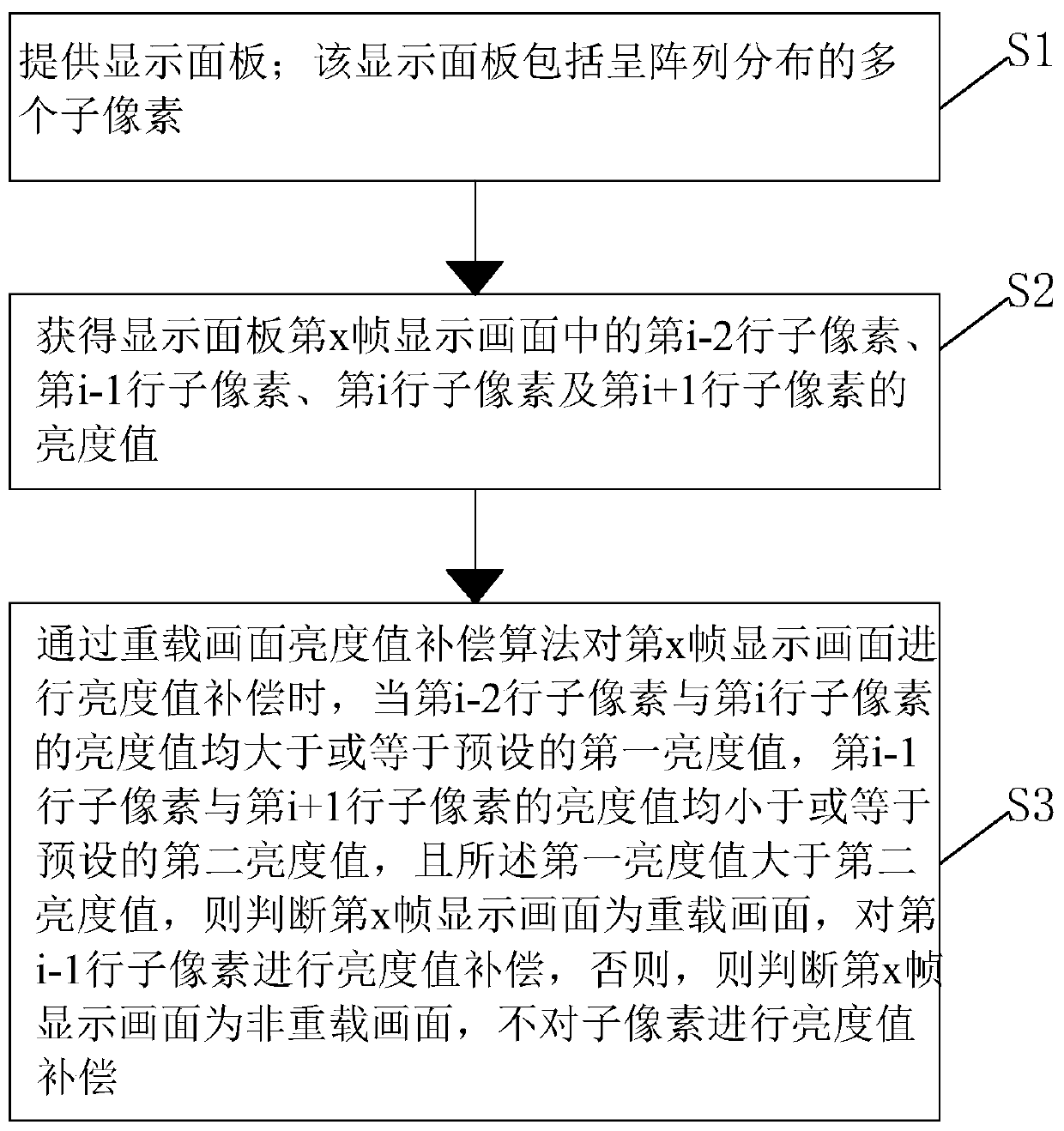
[0030] see figure 1 , the present invention provides a first embodiment of a display panel driving method, comprising the following steps:

[0031] Step S1, providing a display panel 10; the display panel 10 includes a plurality of sub-pixels 20 distributed in an array;

[0032] Step S2, obtaining the luminance values ​​of the sub-pixels 20 in the i-2th row, the sub-pixels 20 in the i-1th row, the sub-pixels 20 in the i-th row, and the sub-pixels 20 in the i+1th row in the display screen of the x-th frame of the display panel 10 , let x, i are both positive integers, and i>=3;

[0033] Step S3, when the brightness value compensation is performed on the display screen of the x-th frame through the overloaded screen brightness value compensation algorithm, when the brightness values ​​of the i-2th row of sub-pixels 20 and the i-th row of sub-pixels 20 are greater than or equal to the preset A luminance value, the luminance values ​​of the sub-pixels 20 in the i-1th row and the...

no. 2 example

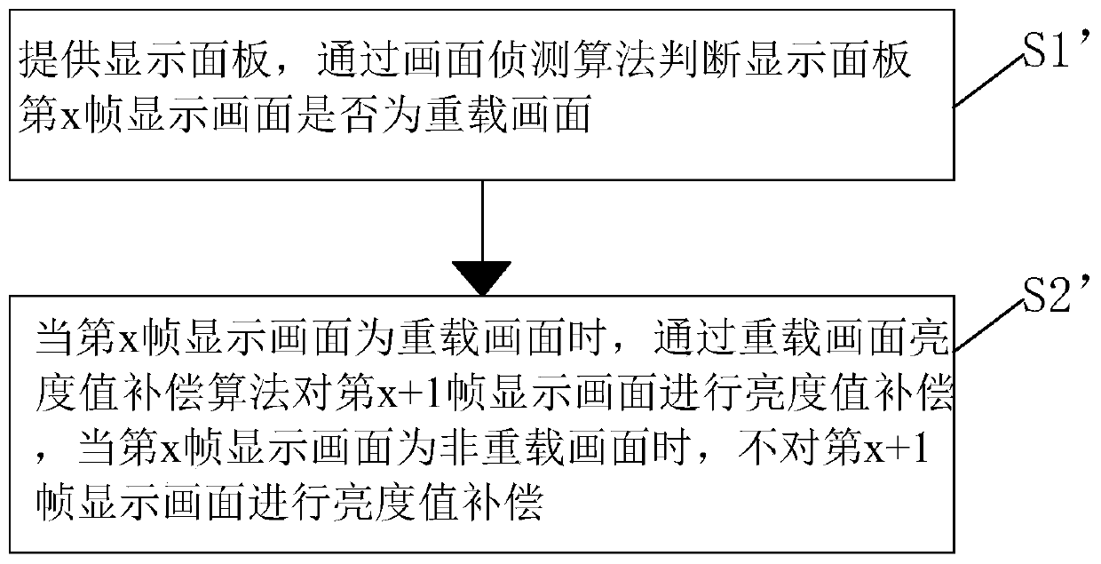
[0040] see figure 2 , the present invention provides a second embodiment of a display panel driving method, comprising the following steps:

[0041] Step S1', providing the display panel 10, and judging whether the display screen of the xth frame of the display panel 10 is an overloaded screen through a screen detection algorithm, and setting x to be a positive integer;

[0042] Step S2', when the display screen of the xth frame is an overloaded screen, perform brightness value compensation on the display screen of the x+1th frame through the brightness value compensation algorithm of the overloaded screen, and when the display screen of the xth frame is a non-overloaded screen, The brightness value compensation is not performed on the x+1th frame display screen.

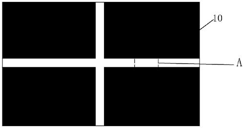
[0043] For clarification, see image 3 and Figure 4 , the display panel 10 includes a plurality of sub-pixels 20 distributed in an array. In the prior art, when the brightness value compensation is performed on...


PUM


Abstract

The present invention provides a display panel driving method. The display panel driving method comprises: performing brightness value compensation only when it is determined that an xth frame of display picture is an overloaded picture, and not performing brightness value compensation when it is determined that the xth frame of display picture is a non-overloaded picture. The present invention avoids a change in the display of the non-overloaded picture caused by miscompensation of the non-overloaded picture, improving the accuracy of compensation.

Description

technical field [0001] The present invention relates to the field of display technology, in particular to a method for driving a display panel. Background technique [0002] Thin Film Transistor (TFT) is the main driving element in current Liquid Crystal Display (LCD) and Active Matrix Organic Light-Emitting Diode (AMOLED). It is related to the display performance of the flat panel display device. [0003] Most of the liquid crystal displays currently on the market are backlight liquid crystal displays, which include a liquid crystal display panel and a backlight module. The working principle of the liquid crystal display panel is to pour liquid crystal molecules between the thin film transistor array substrate (ThinFilm Transistor Array Substrate, TFT Array Substrate) and the color filter (ColorFilter, CF) substrate, and apply pixel voltage on the two substrates respectively. and the common voltage, through the electric field formed between the pixel voltage and the commo...

Claims


Application Information

Patent Timeline
Patent Type & Authority Patents(China)
IPC IPC(8): G09G3/20G09G3/3225G09G3/36
CPCG09G3/20G09G3/3225G09G3/3648
Inventor 王耿何涛
Owner SHENZHEN CHINA STAR OPTOELECTRONICS SEMICON DISPLAY TECH CO LTD
Learn More