
Horizontal pulling force metering device of micro force value dynamometer

A technology of measuring device and dynamometer, which is applied in the direction of measuring device, force/torque/work measuring instrument calibration/test, instrument, etc. Accurate measurement of indication values, etc., to achieve the effect of ensuring measurement accuracy

Inactive Publication Date: 2019-03-19
JIANGXI HONGDU AVIATION IND GRP
View PDF9 Cites 0 Cited by
  • Summary
  • Abstract
  • Description
  • Claims
  • Application Information

AI Technical Summary

Problems solved by technology

However, if the small force dynamometer subjected to horizontal pulling force is installed transposed (horizontal pulling direction is changed to vertical pulling direction), the sensor of the dynamometer will affect the indication value due to the objective existence of the following two factors: 1. The center of gravity of the small force value dynamometer sensor will change when it is placed horizontally and vertically. 2. The directionality of the strain gauge patch of the dynamometer sensor is sensitive to changes, and the pulling direction of the dynamometer sensor in the vertical state There will be a certain difference between the force indication value and the pulling force indication output in the horizontal state, and the smaller the force value, the more sensitive the sensor and the greater the measurement error. The accurate measurement of the indication value of the force cannot meet the requirements of force metrology that "the working state of the force measuring instrument during the measurement verification and calibration should be consistent with the actual working state"

Method used


Image

  • Horizontal pulling force metering device of micro force value dynamometer

Examples


Embodiment Construction

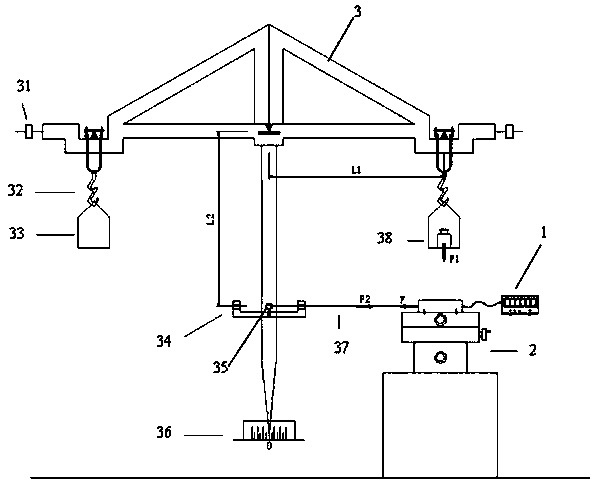
[0021] Such as figure 1 As shown, the micro force value dynamometer horizontal pulling force measurement device of the present invention comprises a dynamometer 1, a working platform 2, and an equiarm balance 3, and the dynamometer 1 is horizontally fixed on the working platform 2, and is characterized in that , a small hole 35 is vertically arranged on the arm of the equal-arm balance 3 balance indicating needle bar, the distance L2 between the small hole 35 and the main knife edge of the balance is equal to the distance L1 between the main knife edge and the hanging weight tray, and the small hole 35 passes through the light and thin Line 37 is connected to the load cell 1 sensor. The small hole 35 is equipped with a horizontal observation hole 34 through which the lightweight thin wire 37 passes to observe the levelness of the lightweight thin wire 37 . The working platform 2 can be adjusted in X, Y, Z three-dimensional directions.

[0022] When the maximum weighing value...


PUM


Abstract

The invention relates to a horizontal pulling force metering device of a micro force value dynamometer. The device comprises the dynamometer 1, a working platform 2 and an equal arm balance 3, whereinthe dynamometer 1 is horizontally fixed to the working platform 2. The device is characterized in that a small hole 35 is vertically formed in a balance indicator rod arm of the equal arm balance 3,the distance L2 between the small hole 35 and a main cutter point of the balance is equal to the distance L1 between the main cutter point and a cutter point of a hanging weight tray, and the small hole 35 is connected with a sensor of the dynamometer 1 through a light string 37. The measuring range of the dynamometer 1 is from 2 mN to10 N. The device meets the demand for transmitting horizontal pulling force values of existing micro force value dynamometers with the measuring range from 2 mN to 10 N and can ensure that the horizontal pulling force values of the micro force value dynamometerswith the standard measuring range from 2 mN to 10N are accurately transmitted. The device has a certain social popularization value and certain social benefits.

Description

technical field [0001] The invention relates to a horizontal tensile force measuring device of a micro force value dynamometer, which belongs to the technical field of measurement. Background technique [0002] Micro force dynamometer refers to a small force measuring instrument with a force measuring range of 2mN to 10N. According to its working state and force direction, it is used to measure vertical tensile force, vertical compressive force, horizontal Tensile force and horizontal compressive force, a total of four situations. The horizontal tensile force measurement device of the micro force dynamometer as defined here refers to the device used to verify or calibrate the horizontal tensile force indication of the micro force dynamometer. Since the minimum measurement force value of the micro force dynamometer is only 2mN, in order to reduce the influence caused by the imperfection of the measuring device, the error of the horizontal pulling force indication value of th...

Claims


Application Information

Patent Timeline
Patent Type & Authority Applications(China)
IPC IPC(8): G01L25/00
CPCG01L25/00
Inventor 袁立新童棣黄为平付莉王航袁超周少文
Owner JIANGXI HONGDU AVIATION IND GRP
Learn More