


Quick Research
Generate reliable direction feasibility study reports for your R&D in just a few steps.

Technical Q&A
Discover and master advanced knowledge NOW. Basics, ideas, possibilities, all at once.

Find Solutions
As an expert in R&D theories, this can generate solutions to your technical problems instantly.

Evaluate Feasibility
Analyze your overall solution with one click, know your potential R&D risks in advance.

Monitor Landscape
Get weekly tech updates, stay abreast of the latest tech innovations and key insights.
Large flow stop valve assembly and stop valve control method
A cut-off valve and large flow technology, applied in the direction of valve lift, valve details, valve device, etc., can solve the problems of reducing the driving energy of the power source, the complex structure of power opening and closing, and the difficulty of setting the power source, etc., to achieve simplified structure and Assembly, simple structure, low cost effect
- Summary
- Abstract
- Description
- Claims
- Application Information
AI Technical Summary
Problems solved by technology
Method used
Image

Examples
Embodiment 1
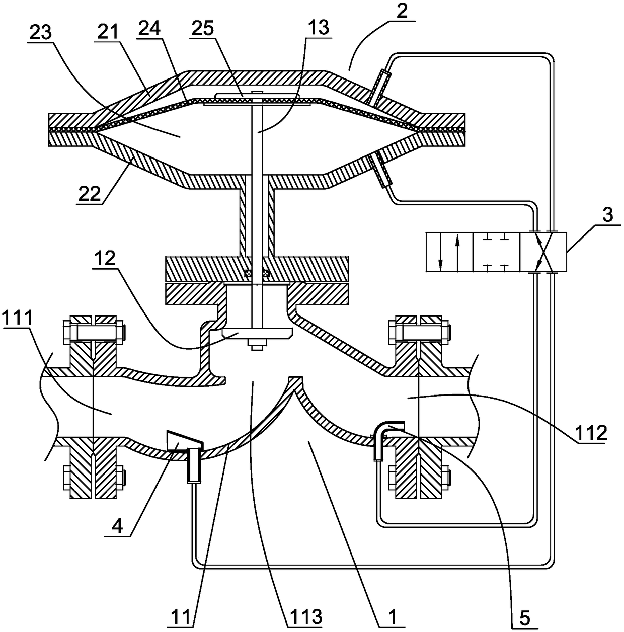
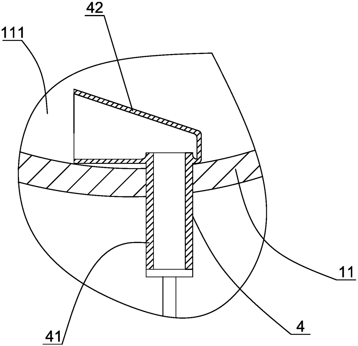
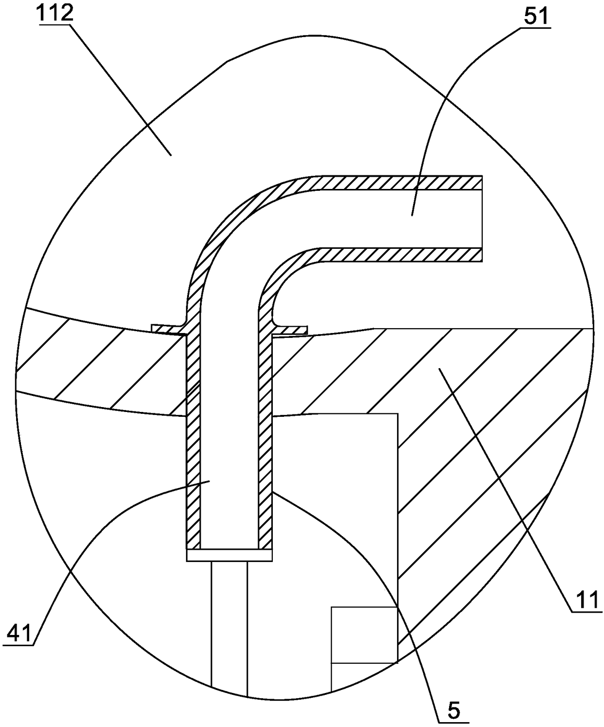
[0030] Example 1. If figure 1 As shown, a large flow cut-off valve assembly includes a cut-off valve 1, the cut-off valve includes a valve housing 11, a valve plate 12 arranged in the valve housing, an input port 111 is provided at one end of the valve housing, and an output port 112 is provided at the other end, A valve hole 113 connected to the input port and the output port is provided in the valve housing corresponding to the position of the valve plate. A valve stem 13 that can move axially is arranged outside the valve housing. One end of the valve rod extends into the valve housing and is connected with the valve plate. The other end of the rod protruding from the valve housing is connected with a valve rod control mechanism. When the valve stem control mechanism moves the valve plate down to the lower position through the valve stem, when the valve plate abuts against and seals the valve hole, the channel between the input port and the output port is cut off, and the s...
Embodiment 2
[0042] Embodiment 2. A method for controlling a large flow shut-off valve, wherein the shut-off valve and the corresponding control mechanism such as figure 1 , figure 2 , image 3 As shown, it specifically includes the following steps:
[0043] a. Lead the fluid on the input port side and the output port side of the shut-off valve connected to the fluid delivery pipeline into two closed pressure chambers of a differential pressure drive device through the pipeline, and set a switchable pressure chamber on the pipeline. The pipeline switching device for the flow direction, the pipeline switching device can adopt a three-position four-way solenoid valve. When the solenoid valve is in the first working position, the fluid on the input port side is introduced into the first pressure chamber of the differential pressure drive device through the solenoid valve, and the fluid on the output port side is introduced into the second pressure chamber of the differential pressure drive...
PUM
 Abstract
Description
Claims
Application Information
 - R&D Engineer
- R&D Manager
- IP Professional
- Industry Leading Data Capabilities
- Powerful AI technology
- Patent DNA Extraction
Browse by: Latest US Patents, China's latest patents, Technical Efficacy Thesaurus, Application Domain, Technology Topic, Popular Technical Reports.
© 2024 PatSnap. All rights reserved.Legal|Privacy policy|Modern Slavery Act Transparency Statement|Sitemap|About US| Contact US: help@patsnap.com