
Man-powered hydraulic pump with high-reliability

A reliable, hydraulic pump technology, applied to the components, pumps, piston pumps, etc. of the pumping device for elastic fluids, can solve the problems of reducing the reliability of the pump, affecting the oil absorption speed, insufficient oil absorption, etc. The effect of speed increase, pressure holding performance improvement, and oil absorption speed increase

Active Publication Date: 2019-03-19
湖北超星液压自动化有限公司
View PDF6 Cites 1 Cited by
  • Summary
  • Abstract
  • Description
  • Claims
  • Application Information

AI Technical Summary

Problems solved by technology

[0005] (1) In order to overcome the problem of oil delivery speed, the following methods are generally adopted: changing the pressure difference, viscosity or pore size, there is no way to change the pressure difference from atmospheric pressure to vacuum. Due to design and manufacturing defects, traditional manual hydraulic pumps are generally used Above all, the viscosity of the delivered oil is limited. Traditional manual hydraulic pumps limit the use of oils marked below No. 32, but the commonly used oil is No. 46, which greatly limits the scope of use of hydraulic oil. Traditional manual hydraulic pumps use more viscous oils. Larger oils (such as No. 46 oil) have slower flow rates
[0006] (2) figure 1 It is the structure and schematic diagram of a traditional human hydraulic pump. At present, the maximum low displacement of a portable human hydraulic pump on the market is 40 ml each time, and there is a limit to the operating frequency, because if the speed is too fast, the oil will be sucked. Insufficient, simply can't reach 40ml each time
If you want to continue to increase the displacement, you can only make it a hydraulic pump station, which is inconvenient to carry
[0007] (3) Limit the temperature of the oil used, because the lower the temperature, the greater the viscosity of the oil, and the viscosity directly affects the oil absorption speed, affecting the use of traditional manual hydraulic pumps
[0008] (4) Multiple working channels are used to make oil absorption faster, but at the same time, the reliability of the pump is reduced due to more channels, and the structural characteristics of the pump also limit the use of more channels
[0009] (5) Since the oil outlet is too large, the sealing line is longer, and the result is: the reliability of the seal is poor

Method used


Image

  • Man-powered hydraulic pump with high-reliability
  • Man-powered hydraulic pump with high-reliability
  • Man-powered hydraulic pump with high-reliability

Examples


Embodiment 1

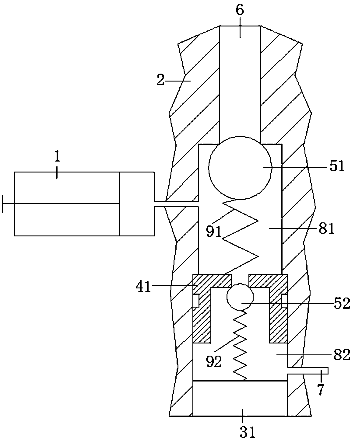
[0037] A high-reliability manual hydraulic pump includes a cylinder body 1, a valve body 2, and an oil inlet hole 6, an oil suction valve chamber 81, an oil outlet valve chamber 82, and an oil outlet hole 7 that are sequentially connected. The oil suction valve chamber, the oil outlet valve chamber and the oil outlet hole are all arranged in the valve body, and an oil suction sealing ball 51 is arranged on the oil inlet of the oil suction valve chamber, and the oil suction sealing ball 51 arranged in the oil suction valve chamber The first elastic member seals the oil-suction sealing ball on the oil inlet of the oil-suction valve chamber; since the cylinder is connected to one side of the oil-suction valve chamber, the piston of the cylinder can be reciprocated by manpower Displacement, when the displacement of the piston increases the volume of the space connected between the oil suction valve chamber and the cylinder body, the pressure of the space connected between the oil s...

Embodiment 2

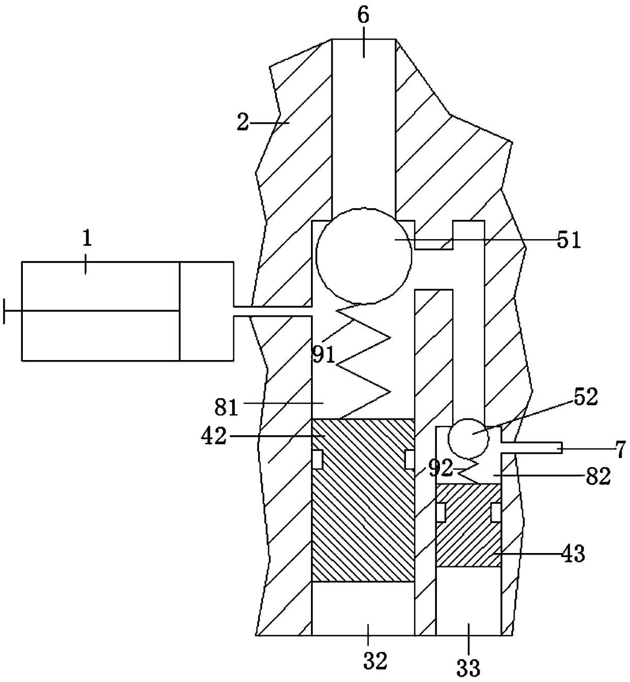
[0045] In this embodiment, the oil suction sealing ball and the oil outlet sealing ball are installed in the valve body through different installation inlets, and the oil inlet of the oil suction valve chamber has a larger diameter than the oil inlet of the oil outlet valve chamber Specifically, the oil outlet valve chamber can be arranged in parallel with the oil suction valve chamber, so designed, it is convenient to make the aperture of the oil inlet of the oil suction valve chamber larger than that of the oil outlet valve chamber in terms of design and manufacture. The aperture of the oil inlet, when designing and manufacturing, make the inner diameter of the oil suction valve chamber larger than the inner diameter of the oil outlet valve chamber to make the aperture of the oil inlet of the oil suction valve chamber larger than the oil inlet of the oil outlet valve chamber Similarly, the aperture size of the oil inlet and outlet of the valve body can be changed. The increas...

Embodiment 3

[0049] In this embodiment, the oil suction sealing ball and the oil outlet sealing ball are installed in the valve body through different installation inlets, and the oil inlet of the oil suction valve chamber has a larger diameter than the oil inlet of the oil outlet valve chamber Specifically, the oil outlet valve chamber and the oil suction valve chamber are vertically arranged, so designed, it is convenient to make the aperture of the oil inlet of the oil suction valve chamber larger than the inlet of the oil outlet valve chamber in terms of design and manufacture. The aperture of the oil port, when designing and manufacturing, make the inner diameter of the oil suction valve chamber larger than the inner diameter of the oil outlet valve chamber to make the aperture of the oil inlet of the oil suction valve chamber larger than that of the oil inlet of the oil outlet valve chamber The aperture, similarly, can change the aperture size of the oil inlet and outlet of the valve ...


PUM


Abstract

The invention belongs to the technical field of hydraulic pumps and discloses a man-powered hydraulic pump with a high-reliability. The man-powered hydraulic pump comprises a cylinder body, a valve body, an oil inlet hole, an oil suction valve chamber, an oil outlet valve chamber and an oil outlet hole, wherein the oil inlet, the oil suction valve chamber, the oil outlet valve chamber and the oiloutlet hole are communicated in sequence and are arranged in the valve body; an oil suction sealing ball is arranged on an oil inlet of the oil suction valve chamber; the oil suction sealing ball is sealed and plugged in the oil inlet of the oil suction valve chamber through a first elastic assembly arranged in the oil suction valve chamber; compared with the prior art, the oil conveying speed ofthe man-powered hydraulic pump is improved by multiple times, the pressure maintaining performance is obviously improved, and the device can be designed to be portable.

Description

technical field [0001] The invention belongs to the technical field of hydraulic pumps, and in particular relates to a highly reliable human hydraulic pump. Background technique [0002] The human hydraulic pump has a long history of application. Its principle and structure are familiar and taken for granted by most people in the industry. It is mainly composed of three parts: oil inlet check valve, oil outlet check valve and piston cylinder (such as figure 1 Shown), due to factors such as hydraulic pressure and manufacturing considerations, the traditional manual hydraulic pump is designed so that the bore of the oil inlet check valve is smaller than the bore of the oil outlet check valve, and this design has not changed so far. [0003] The defective of this design is very obvious, and performance is also very prominent in practical application, and that is that the oil discharge speed can not have good performance because of the influence of many factors. In addition, si...

Claims


Application Information

Patent Timeline
Patent Type & Authority Applications(China)
IPC IPC(8): F04B9/14F04B53/10F04B53/16
CPCF04B9/14F04B53/1002F04B53/16
Inventor 戴炎昌
Owner 湖北超星液压自动化有限公司
Learn More