
Drive mechanism for a comfort drive of a motor vehicle and a comfort drive

A technology of driving mechanism and driving device, which is applied in the direction of transmission device, electromechanical device, special position of vehicle, etc., can solve problems such as noise and unpopularity, and achieve the effect of saving space

Active Publication Date: 2022-07-05
ROBERT BOSCH GMBH
View PDF11 Cites 0 Cited by
  • Summary
  • Abstract
  • Description
  • Claims
  • Application Information

AI Technical Summary

Problems solved by technology

Although known axial bearings can axially support the worm wheel on the inner housing, the worm wheel has an axial play inside the inner housing
Although in principle existing component tolerances can be compensated for by such an axial play, in particular when reversing the direction of rotation of the drive, the axial impact of the worm wheel on the inner housing can cause damage. Unwelcome noise occurs

Method used


Image

  • Drive mechanism for a comfort drive of a motor vehicle and a comfort drive
  • Drive mechanism for a comfort drive of a motor vehicle and a comfort drive
  • Drive mechanism for a comfort drive of a motor vehicle and a comfort drive

Examples


Embodiment Construction

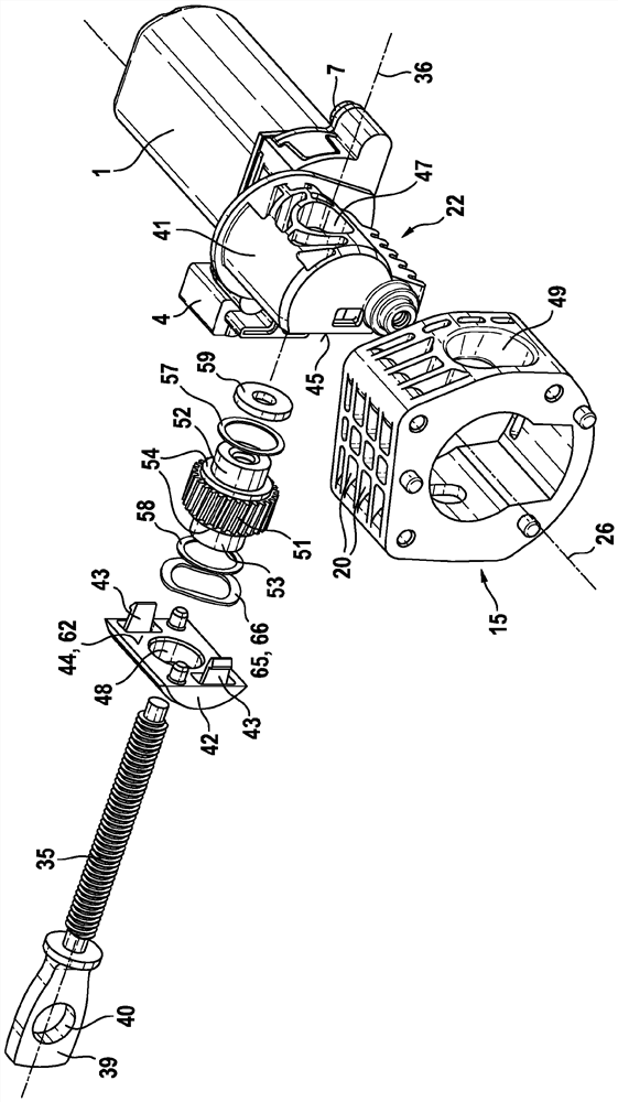
[0019] exist figure 1 A drive mechanism 10 for a comfort drive of a motor vehicle is shown. Such a comfort drive can be designed, for example, in the form of a seat adjustment drive or a steering column adjustment drive. However, the present invention should not be limited to such an application of the drive mechanism 10 .

[0020] The drive mechanism 10 comprises an electric motor 1 with a housing, for example made of metal, produced by deep-drawing in the form of a pole pot housing 2, and a connecting flange 3, which is connected. The flange has a connector body 4 for making electrical contact with the electric motor 1 . The drive shaft 5 of the electric motor protrudes from the pole pot housing 2 or the connecting flange 3 of the electric motor 1 ( figure 2 ). The drive shaft 5 has a worm gear 6 in the region protruding from the pole pot housing 2 or the connecting flange 3 .

[0021] The pole pot housing 2 of the electric motor 1 or its connecting flange 3 is connect...


PUM


Abstract

The invention relates to a drive ( 10 ) for a comfort drive of a motor vehicle, which has an electric motor ( 1 ) and a toothing ( 6 ) arranged on the drive shaft ( 5 ), wherein , the electric motor has a drive shaft ( 5 ), the toothing cooperates with a transmission element ( 27 ) arranged in the inner housing ( 22 ), wherein the transmission element ( 27 ) has a longitudinal axis ( 36 ) The drive element ( 35 ) of the (22) is arranged in a receptacle (18) of the outer housing (15), and wherein the outer housing (15) is configured with an interface for connecting the drive mechanism (10) to the carrier structure of the motor vehicle ( 100) Connected.

Description

technical field [0001] The invention relates to a drive mechanism for a comfort drive of a motor vehicle according to the preamble of claim 1 . Furthermore, the invention relates to a comfort drive with the drive according to the invention. Background technique [0002] A drive mechanism according to the preamble of claim 1 is known from the applicant's supplementary publication DE 10 2015 215 428 A1. The disclosed drive mechanism is distinguished by the inner housing for receiving the transmission mechanism. The transmission mechanism includes a worm gear, the teeth of which cooperate with the drive shaft of the electric motor. A threaded main shaft is received in the internal thread in the longitudinal bore of the worm gear, the threaded main shaft is externally threaded so as to convert the rotational movement of the worm gear into a linear movement of the threaded main shaft. The threaded spindle is in turn connected at least indirectly to the element to be adjusted, ...

Claims


Application Information

Patent Timeline
Patent Type & Authority Patents(China)
IPC IPC(8): F16H25/20B60N2/06H02K7/06
CPCB60N2/067F16H25/20H02K7/06F16H2025/2084F16H2025/2445F16H2025/2031H02K7/1166B60N2/929
Inventor C.安格雷尔
Owner ROBERT BOSCH GMBH
Learn More