Disposal utensils
一种处置器具、面具的技术,应用在加热外科器械、手术器械的零部件、医药科学等方向,能够解决难以缩短处置时间、耗费时间等问题,达到缩短处置时间、低创处置的效果
- Summary
- Abstract
- Description
- Claims
- Application Information
AI Technical Summary
Problems solved by technology
Method used
Image

Examples
Embodiment approach 1
[0026] [Outline structure of disposal system]
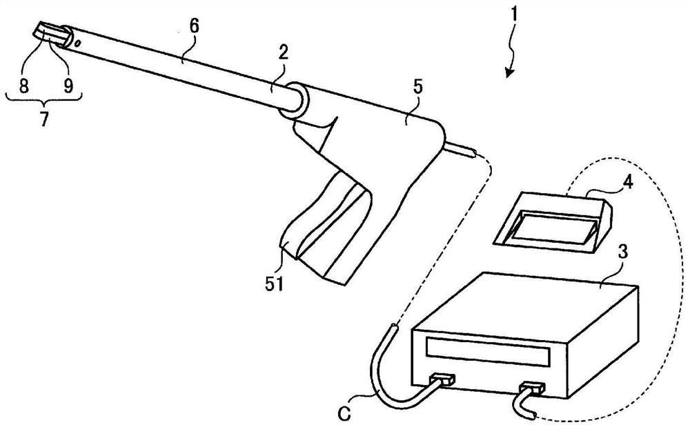
[0027] figure 1 It is a figure which shows the treatment system 1 which concerns on Embodiment 1 of this invention.
[0028] The treatment system 1 can treat living tissue (joint (or anastomosis) and resection, etc.) by applying energy (thermal energy and electric energy (high-frequency energy)) to the living tissue. Such as figure 1 As shown, the treatment system 1 includes a treatment instrument 2 , a control device 3 and a foot switch 4 .
[0029] [structure of disposal appliance]
[0030] The treatment instrument 2 is, for example, a linear surgical and medical treatment instrument for treating living tissue through the abdominal wall. Such as figure 1 As shown, the treatment instrument 2 includes a handle 5 , a rod part 6 and a grip 7 .
[0031] The handle 5 is a part where the operator holds the treatment tool 2 with his hand. Such as figure 1 As shown, the handle 5 is provided with an operating knob 51 .
[0032] ...
Embodiment approach 2
[0086] Next, Embodiment 2 of the present invention will be described.
[0087] In the description of Embodiment 2, the same reference numerals are assigned to the same configurations as in Embodiment 1 above, and detailed description thereof will be omitted or simplified.
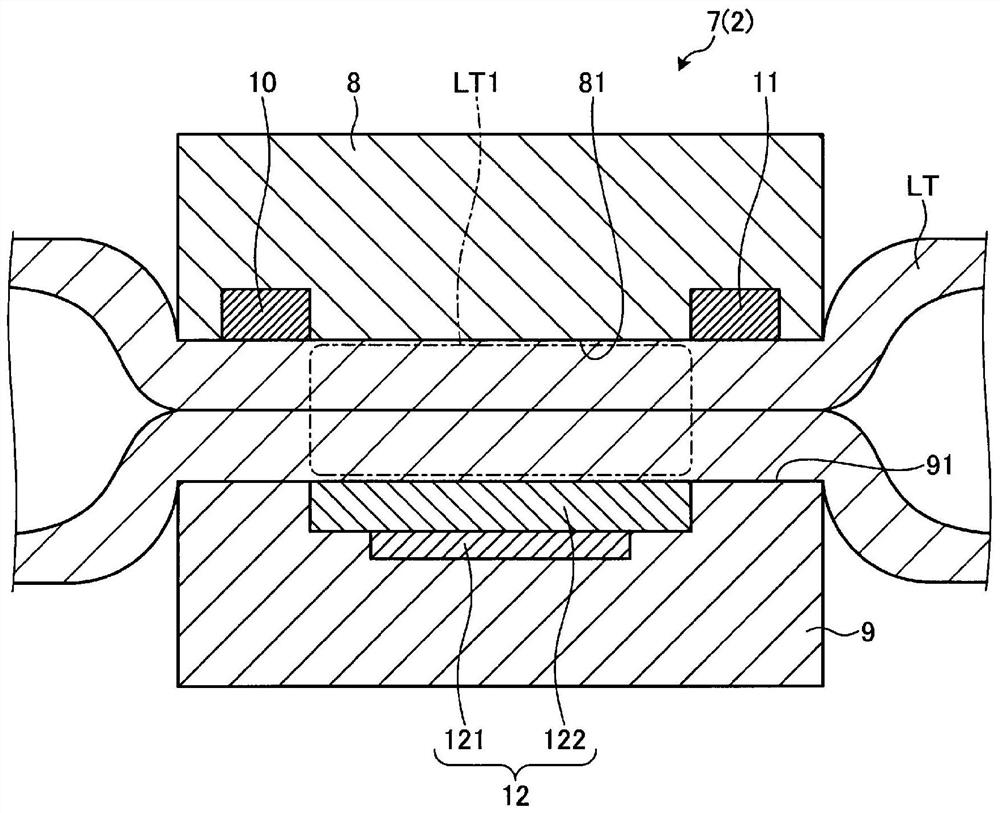
[0088] Figure 6 It is a figure which shows the grip part 7A which comprises the treatment instrument 2A which concerns on Embodiment 2 of this invention. in particular, Figure 6 With image 3 Corresponding sectional view.
[0089] In the treatment instrument 2A of the second embodiment, if Figure 6 As shown, with respect to the treatment instrument 2 described in Embodiment 1 above ( image 3 ), the setting positions of the first electrode and the second electrode of the present invention are different.
[0090] In one jaw 8 of Embodiment 2, on one gripping surface 81, such as Figure 6 As shown, the first and second electrodes 10, 11 are not provided. One gripping surface 81 of the second embodi...
Embodiment approach 3
[0100] Next, Embodiment 3 of the present invention will be described.
[0101] In the description of Embodiment 3, the same reference numerals are assigned to the same configurations as in Embodiment 1 above, and detailed description thereof will be omitted or simplified.
[0102] Figure 7 It is a figure which shows the grip part 7B which comprises the treatment instrument 2B in Embodiment 3 of this invention. in particular, Figure 7 With image 3 corresponding figure.
[0103] In the treatment instrument 2B of the third embodiment, if Figure 7 As shown, with respect to the treatment instrument 2 described in Embodiment 1 above ( image 3 ), the arrangement positions and formation methods of the first electrode and the second electrode of the present invention are different.
[0104] In one jaw 8 of Embodiment 3, as Figure 7 As shown, one gripping surface 81 has a flat shape without first and second electrodes 10 and 11 as in Embodiment 2 above. The non-adhesive in...
PUM
 Abstract
Description
Claims
Application Information
 - R&D
- Intellectual Property
- Life Sciences
- Materials
- Tech Scout
- Unparalleled Data Quality
- Higher Quality Content
- 60% Fewer Hallucinations
Browse by: Latest US Patents, China's latest patents, Technical Efficacy Thesaurus, Application Domain, Technology Topic, Popular Technical Reports.
© 2025 PatSnap. All rights reserved.Legal|Privacy policy|Modern Slavery Act Transparency Statement|Sitemap|About US| Contact US: help@patsnap.com