
Wireless synchronous trigger device, electric tool, and system and method for combining and synchronizing tools

An electric tool and synchronous triggering technology, which is applied in the direction of manufacturing tools, portable motorized devices, general control systems, etc., can solve the problems of cumbersome usage, high cost, and inability to meet the needs of the development of hand-held DC electric tools, etc., reaching the scope of application Wide, simple structure effect

Pending Publication Date: 2019-03-15
SKYBEST ELECTRIC APPLIANCE SUZHOU CO LTD
View PDF0 Cites 1 Cited by
  • Summary
  • Abstract
  • Description
  • Claims
  • Application Information

AI Technical Summary

Problems solved by technology

[0003] The combined power tool systems with synchronization function currently on the market are usually AC power tools, which transmit signals such as the working status of one AC power tool to another AC power tool through cables or wireless communication, and cannot communicate with DC power tools. The tool realizes synchronous work, which cannot meet the needs of the current development of hand-held DC electric tools
For example, by improving the wireless remote control socket to realize the synchronous work of combined electric tools, the use method is cumbersome and the cost is relatively high

Method used


Image

  • Wireless synchronous trigger device, electric tool, and system and method for combining and synchronizing tools
  • Wireless synchronous trigger device, electric tool, and system and method for combining and synchronizing tools
  • Wireless synchronous trigger device, electric tool, and system and method for combining and synchronizing tools

Examples


Embodiment Construction

[0070] The present invention will be described in detail below in conjunction with specific embodiments shown in the accompanying drawings. However, these embodiments do not limit the present invention, and any structural, method, or functional changes made by those skilled in the art according to these embodiments are included in the protection scope of the present invention.

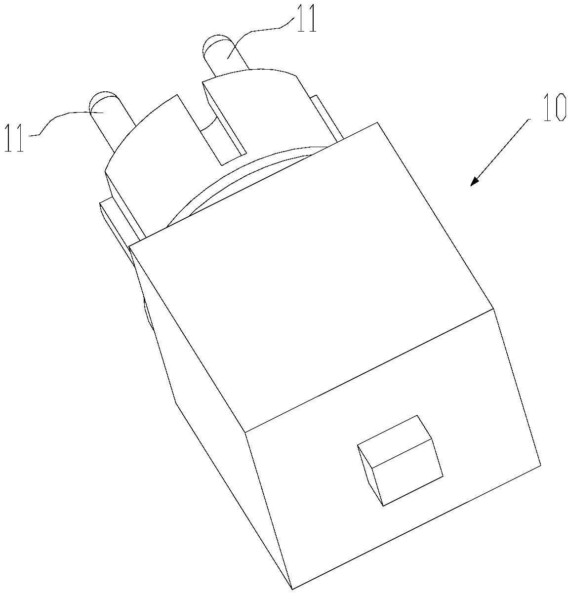
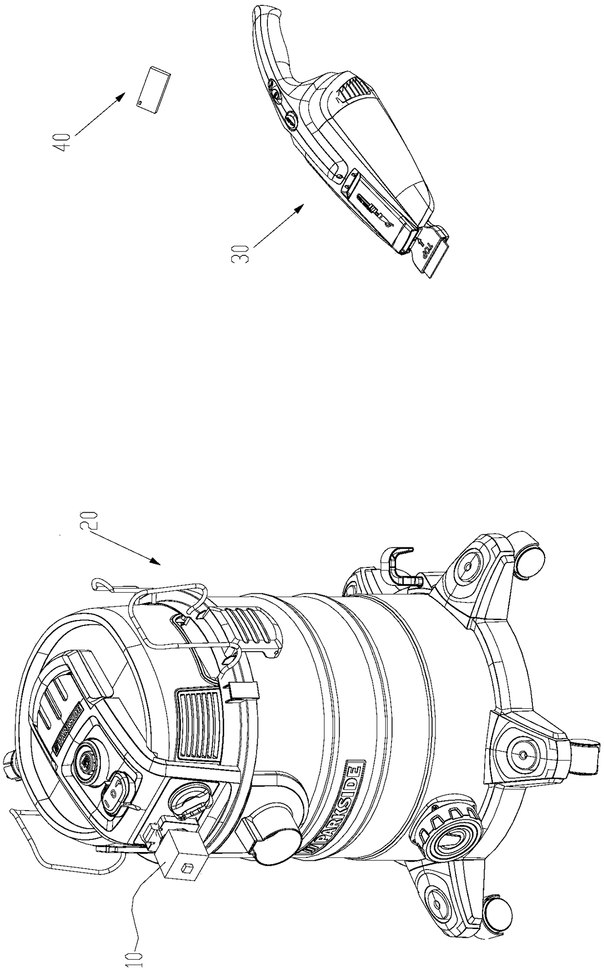
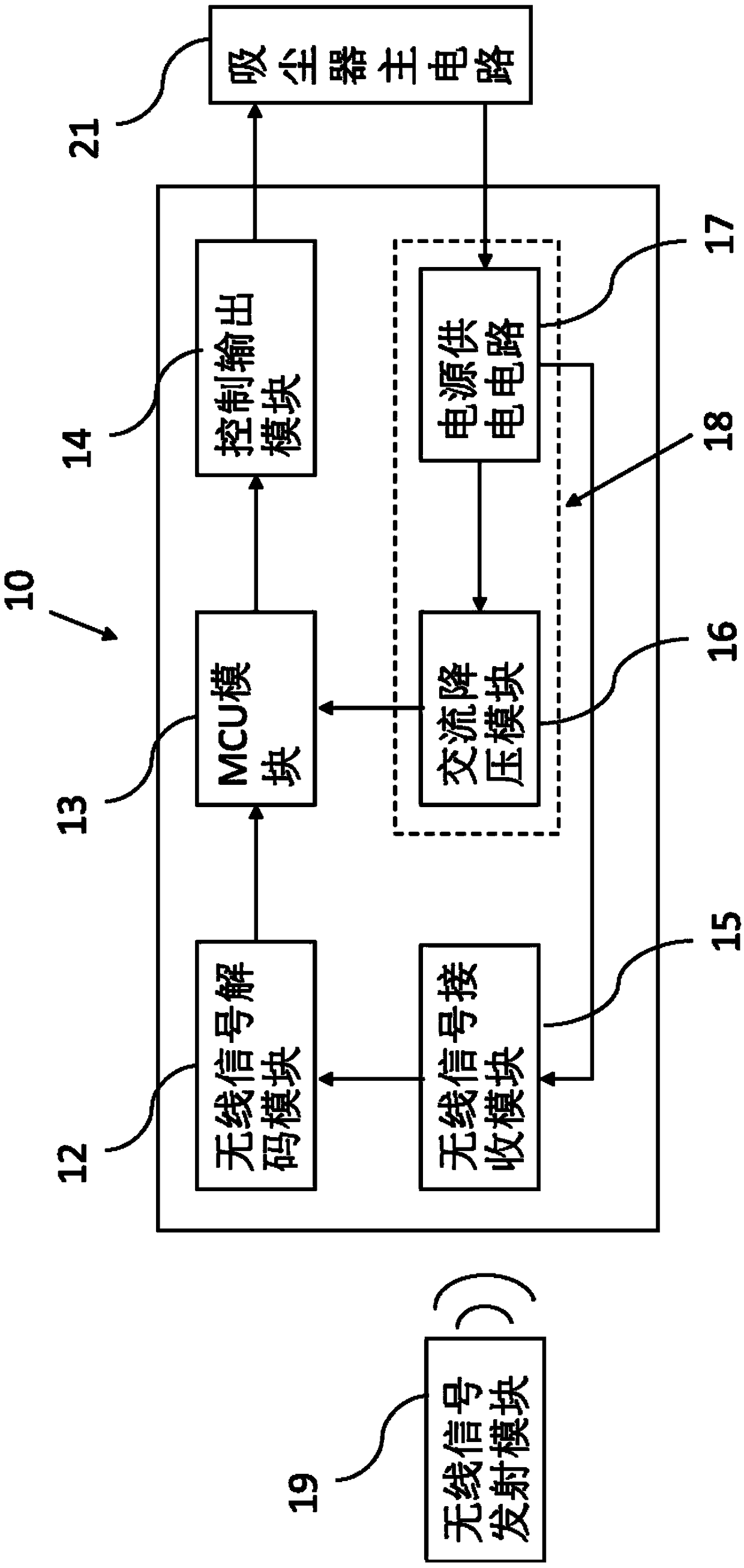
[0071] refer to Figure 1-Figure 3 , in one embodiment of the present invention, a wireless synchronous trigger device 10, including: a voltage conversion module 18, used to provide working power for each circuit module of the wireless synchronous trigger device;

[0072] an electrical connector 11, the electrical connector 11 is operable to be electrically connected to or disconnected from the main circuit 21 of the first electric tool 20;

[0073] Wireless signal transmitting module 19, described wireless signal transmitting module 19 is operably triggered to be used for sending wireless synchronous...


PUM


Abstract

The invention discloses a wireless synchronous trigger device, an electrical tool, and a system and method for combining and synchronizing tools. When the wireless synchronization trigger device is assembled on a first electric tool, electric connectors are electrically connected with a main circuit of the first electric tool. The wireless synchronization trigger device can receive a wireless synchronization signal sent by a wireless signal transmitting module and output a synchronization control signal to the first electric tool to control the working state of the first electric tool to be synchronized with the working state of a second electric tool. The invention only adds the wireless synchronization triggering device which is detachably assembled on the first electric tool, thus realizing synchronous operation of the alternating current electric tool and the direct current electric tool without changing the circuit and structure of the original first electric tool. The invention has the advantages of wide application range, simple structure, convenient operation by users and low cost.

Description

technical field [0001] The invention relates to a wireless synchronous trigger device, an electric tool, a combined synchronous tool system and a method, in particular to an easy-to-use and low-cost wireless synchronous trigger device, an electric tool, a combined synchronous tool system and a method. Background technique [0002] In some usage scenarios of electric tools, it is sometimes necessary to use multiple electric tools to complete the same task. For example, when using a grinder or cutting tool, it is necessary to keep the workbench clean, or to reduce the scattering of dust, which requires the use of a vacuum cleaner to collect it in real time. Dust generated when cutting or polishing. [0003] The combined power tool systems with synchronization function currently on the market are usually AC power tools, which transmit signals such as the working status of one AC power tool to another AC power tool through cables or wireless communication, and cannot communicate...

Claims


Application Information

Patent Timeline
Patent Type & Authority Applications(China)
IPC IPC(8): B25F5/00G05B19/042
CPCG05B19/0423B25F5/00
Inventor 陈泓陈飞陈志鑫
Owner SKYBEST ELECTRIC APPLIANCE SUZHOU CO LTD
Learn More