
A Method of Forecasting the Flow Rate of Large-Scale Low-Head Pumps

A technology of pump flow and low lift, applied in instruments, geometric CAD, calculation, etc., can solve the problems of measurement accuracy or high cost, high measurement accuracy, limited wide application, etc.

Active Publication Date: 2019-07-19
HOHAI UNIV
View PDF5 Cites 0 Cited by
  • Summary
  • Abstract
  • Description
  • Claims
  • Application Information

AI Technical Summary

Problems solved by technology

[0003] At present, the flow data of large-scale low-lift water pumps are basically obtained by calculating the performance curve of the prototype pump device after the actual measurement of the water level of the inlet and outlet pools, the head of the device and the performance curve of the model pump device. Limitation, the original model can not unify the similarity criteria, resulting in the scale effect, data fitting and interpolation errors in the original model similar conversion, which makes it difficult to achieve high measurement accuracy by this method of flow calculation; the field flow test method mainly has five holes Probe flow measurement method, bypass flow pipe flow measurement method, internally attached ultrasonic flowmeter, flow velocity meter method, brine concentration method, etc. These methods are affected by measurement accuracy or high cost, which limits their application in large low-lift water pumps. Widely used in water flow channels; scholars have calculated the relationship between flow and pressure difference through theoretical analysis, and summarized the flow measurement method of differential pressure in water inlet channels. This is a relatively simple flow measurement method, which is more suitable for large-scale low-lift On-site flow monitoring of water pumps, but it needs to determine the relationship between flow and differential pressure in advance. Usually, the flow meter method or brine concentration method of pump station on-site testing is used to determine the relationship between flow and differential pressure. This calibration method has a large workload and is limited. Many conditions and errors are difficult to meet the accuracy requirements, making it difficult to popularize and apply the differential pressure flow measurement method of the inlet channel. In addition, the selection of pressure measurement points also limits the simplicity of the flow measurement method. In recent years, CFD numerical calculations have been used in fluid dynamics. There are many applications. Some scholars try to obtain the coefficient of the field measured flow rate and differential pressure through CFD calculations to predict the measured flow rate of the water pump inlet channel. The method first obtains the flow rate Q through a physical model test. mt and differential pressure ΔP mt The relationship coefficient k mt , and then obtain the model flow rate Q in the numerical calculation through numerical calculation mc and differential pressure ΔP mc The relationship coefficient k mc , and then obtain the prototype through numerical calculation. In the numerical calculation, the flow Q pc and differential pressure ΔP pc The relationship coefficient k pc , and finally through k mt with k mc k pc get k pt , and finally obtain the field measured flow through the differential pressure formula
The unscientific method of obtaining the flow measured on site through CFD calculation above is that the truncation error of the fitting equation cannot be determined according to the proportional ratio. Secondly, under the premise of ensuring the correct turbulence model, grid quality and boundary layer processing method, the computer cannot carry large-scale low For the calculation of the huge amount of grids of the lift pump prototype, the computer hardware requirements can only be met by enlarging the grid size, which greatly reduces the accuracy of CFD numerical calculations

Method used


Image

  • A Method of Forecasting the Flow Rate of Large-Scale Low-Head Pumps
  • A Method of Forecasting the Flow Rate of Large-Scale Low-Head Pumps

Examples


Embodiment Construction

[0041] The present invention will be described in further detail below in conjunction with the accompanying drawings and specific embodiments.

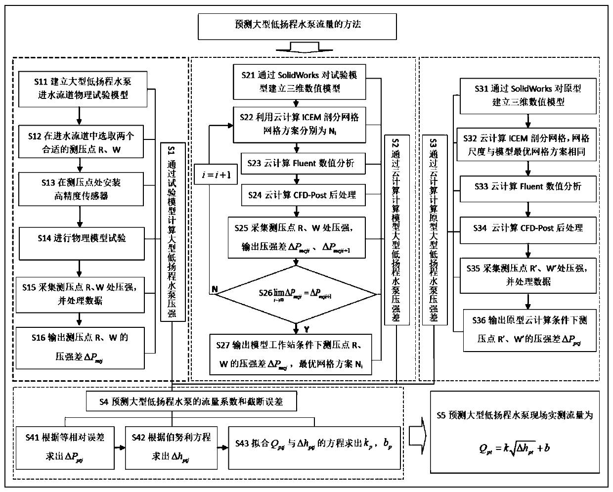
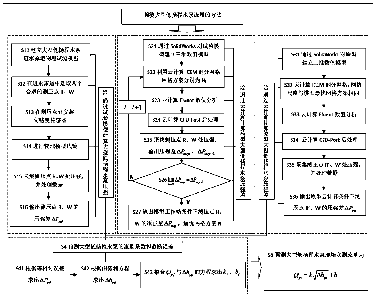
[0042] Such as figure 1 Shown is a flow chart of the method for predicting the flow rate of a large-scale low-lift water pump of the present invention. The method for predicting the flow rate of a large-scale low-lift water pump in this embodiment first establishes a physical test model of a large-scale low-lift water pump inlet flow channel, selects two suitable pressure measurement points in the water inlet flow channel, and installs high-precision sensors at the two pressure measurement points. , collect the pressures of the two pressure measuring points in the physical model test under different flow conditions, and obtain the pressure difference of each flow rate of the two pressure measuring points under the physical model test conditions; then use the three-dimensional modeling software SolidWorks to build a model of large-scal...


PUM


Abstract

The invention discloses a method for predicting the flow rate of a large-scale low-head pump, which comprises the following steps: S1, calculating the pressure difference of the large-scale low-head pump through a test model; S2, calculating the pressure difference of large-scale low-head pump by cloud computing model; S3, calculating the pressure difference of the prototype large-scale low-head pump by cloud computing; S4, predicting discharge coefficient and truncation error of large-scale low-head pump; S5 predicts the field measured discharge of large-scale low-lift pumps. Cloud computingis introduced into the method of predicting the flow of large-scale low-head pumps, The numerical method of cloud computing solves the problem that the workstation can not compute because the model mesh size is used to generate huge mesh in the prototype numerical computation, and avoids the problem that the simulation results are not accurate due to the hardware problem which will increase the grid spacing. The invention can accurately predict the field measured flow rate of the large-scale low-lift pump, thereby determining the efficiency of the pump device and the unit energy consumption inthe pump station engineering, and scientifically and accurately completing the performance test of the pump device.

Description

technical field [0001] The invention belongs to the field of water conservancy engineering, in particular to a method for predicting the flow rate of a large-scale low-lift water pump. Background technique [0002] The flow rate of large-scale low-head water pumps is a key parameter to determine the efficiency and unit energy consumption of pumping station devices. It is related to whether the performance test of prototype pump devices can be completed scientifically and accurately, so as to verify the research, design and manufacturing level of large-scale pump devices. Due to the short inlet channel of the large low-lift water pump, the irregular cross-section and the cast-in-place reinforced concrete, the measurement and monitoring of its flow has always been an unsolved problem in the field of pumping station engineering. [0003] At present, the flow data of large-scale low-lift water pumps are basically obtained by calculating the performance curve of the prototype pum...

Claims


Application Information

Patent Timeline
Patent Type & Authority Patents(China)
IPC IPC(8): G06F17/50
CPCG06F30/13
Inventor 朱晓明于永海张伟
Owner HOHAI UNIV
Learn More