
Polarized infrared sensor based on metasurface fbar resonant frequency temperature drift characteristics

An infrared sensor and resonant frequency technology, applied in the field of infrared sensing, can solve the problems of low spatial resolution, low energy utilization rate, large volume and weight, etc., and achieve the effects of small size, optimized structure and performance, and low cost

Active Publication Date: 2020-09-08
CHANGCHUN INST OF OPTICS FINE MECHANICS & PHYSICS CHINESE ACAD OF SCI
View PDF9 Cites 0 Cited by
  • Summary
  • Abstract
  • Description
  • Claims
  • Application Information

AI Technical Summary

Problems solved by technology

The time-sharing polarization sensor obtains information of different polarization directions at different time points by rotating the polarizer. Although this technology is simple, its structure is unstable and it is easy to produce virtual images; the amplitude-sharing polarization sensor is composed of multiple different focal planes. A focal plane optical path has polarization polarizers in different directions. This system can effectively reduce the virtual image caused by target movement, but the energy utilization rate is low, the volume is large, and the price is expensive. The image is projected to different areas of the focal plane. Compared with the sub-amplitude system, its optical path is shorter, and the optical path is not easily disturbed after alignment, but its spatial resolution is low and its volume and weight are large.

Method used


Image

  • Polarized infrared sensor based on metasurface fbar resonant frequency temperature drift characteristics
  • Polarized infrared sensor based on metasurface fbar resonant frequency temperature drift characteristics
  • Polarized infrared sensor based on metasurface fbar resonant frequency temperature drift characteristics

Examples


Embodiment Construction

[0035] In order to understand the above-mentioned purpose, features and advantages of the present invention more clearly, the present invention will be further described in detail below in conjunction with the accompanying drawings and specific embodiments.

[0036] In the following description, many specific details are set forth in order to fully understand the present invention. However, the present invention can also be implemented in other ways different from those described here. Therefore, the protection scope of the present invention is not limited by the specific details disclosed below. EXAMPLE LIMITATIONS.

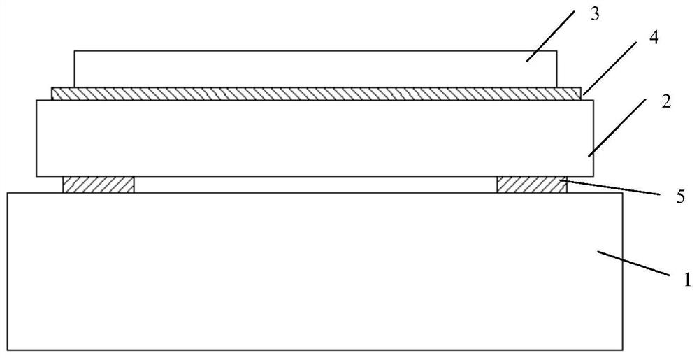
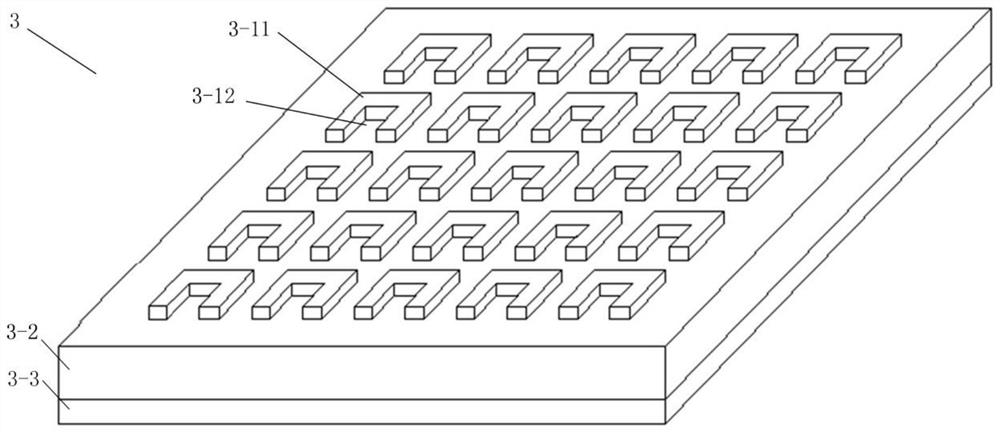
[0037] A polarized infrared sensor based on the temperature drift characteristics of the resonant frequency of the metasurface FBAR, such as figure 1 As shown, the infrared sensor also includes a readout integrated circuit substrate 1 (also known as ROIC substrate), a thin film bulk acoustic resonator 2, a metal reflection layer 3-3, a dielectric layer 3-2 and a...


PUM


Abstract

The polarized infrared sensor based on the temperature drift characteristics of the resonant frequency of the metasurface FBAR relates to the field of infrared sensing technology, and solves the problems of low absorption rate and the need to improve the structure and performance of the infrared polarization sensor in the prior art, including sequentially connected readout integration A circuit substrate, a thin film bulk acoustic wave resonator, a metal reflection layer, a medium layer and a metal array layer. The metal array layer is composed of a plurality of metal units with the same characteristic direction. The uncooled infrared sensor of the present invention utilizes the metal reflective layer, the medium layer and the metal array layer to realize the enhanced absorption of the infrared spectrum, and the absorbed energy acts on the thin film bulk acoustic resonator to greatly increase the absorption rate of the uncooled infrared sensor. The array layer realizes polarized light absorption, and optimizes the infrared polarization sensor in terms of structure and performance; it is connected in an integrated manner, with small volume, weight and low cost; it has the advantages of traditional uncooled infrared sensing, and at the same time has fast response and high sensing sensitivity.

Description

technical field [0001] The invention relates to the technical field of infrared sensing, in particular to a polarized infrared sensor based on the temperature drift characteristics of the resonant frequency of a metasurface FBAR. Background technique [0002] Uncooled infrared sensors are also called room temperature sensors, which can work at room temperature without refrigeration, so they have the advantages of being more portable. Uncooled infrared sensors are generally thermal sensors, that is, they work by sensing the thermal effect of infrared radiation. Because the uncooled infrared sensor omits the bulky and expensive refrigeration mechanism, it has advantages over cooled infrared sensors in terms of volume, weight, life, cost, power consumption, startup speed and stability. However, there is a gap in response time and sensing sensitivity compared with cooled infrared sensors. [0003] In recent years, with the development of micro-nano sensing technology, the appl...

Claims


Application Information

Patent Timeline
Patent Type & Authority Patents(China)
IPC IPC(8): G01J5/58G01J5/02
CPCG01J5/02G01J5/0265G01J5/58G01J5/59
Inventor 陶金梁中翥孟德佳梁静秋秦余欣吕金光史晓燕秦正
Owner CHANGCHUN INST OF OPTICS FINE MECHANICS & PHYSICS CHINESE ACAD OF SCI
Learn More