Rotary soot blower device and soot blower method for improving uniformity of denitrification inlet flue flow field

A technology of inlet flue and soot blowing device, which is applied in the directions of combustion method, combustion product treatment, removal of solid residue, etc., can solve the problem of soot accumulation in the flue, avoid damage, prevent a large number of deposits, and expand the coverage of soot blowing range effect

Pending Publication Date: 2019-03-12
HUADIAN ELECTRIC POWER SCI INST CO LTD
View PDF6 Cites 2 Cited by
  • Summary
  • Abstract
  • Description
  • Claims
  • Application Information

AI Technical Summary

Problems solved by technology

[0006] The purpose of the present invention is to effectively solve the problem of serious ash accumulation in the flue of the denitrification inlet of a coal-fired power plant, save manpower and time for cleaning ash, improve the uniformity of the flow field of the denitrification device, and prevent the damage of the flue caused by soot blowing in a fixed direction, and then provide A rotary soot blowing device and its soot blowing method for improving the flow field uniformity of the denitrification inlet flue

Method used


Image

  • Rotary soot blower device and soot blower method for improving uniformity of denitrification inlet flue flow field
  • Rotary soot blower device and soot blower method for improving uniformity of denitrification inlet flue flow field
  • Rotary soot blower device and soot blower method for improving uniformity of denitrification inlet flue flow field

Examples


Embodiment Construction

[0020] The present invention will be further described in detail below in conjunction with the accompanying drawings and examples. The following examples are explanations of the present invention and the present invention is not limited to the following examples.

[0021] Example.

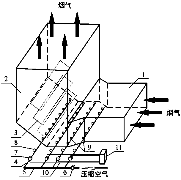
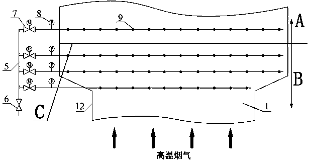
[0022] see Figure 1 to Figure 4 , a rotary soot blowing device for improving the uniformity of the flue flow field at the denitrification inlet, including a compressed air main pipe 5, a compressed air branch pipe 4, a branch pipe pressure monitoring system, a soot blowing device, a compressed air main pipe manual switch valve 6, and a communication cable 10. Branch pipe purge switch and purge time control system.

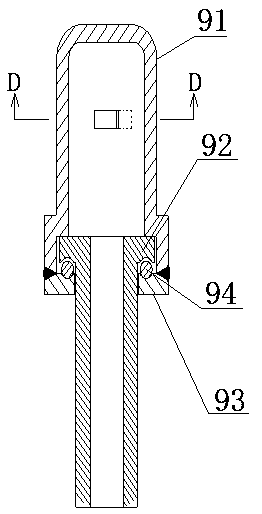
[0023] As a preference, in this embodiment, the pressure gauge 8 is selected for the branch pipe pressure monitoring system, the rotary soot blowing cap 9 is used for the soot blowing device, the compressed air branch pipe electromagnetic switch valve 7 is used for the branch pipe pur...


PUM


Abstract

The invention relates to a rotary soot blower device and a soot blower method for improving the uniformity of a denitrification inlet flue flow field, and belongs to the technical field of coal-firedpower plant flue soot deposition prevention. The rotary soot blower device comprises a compressed air mother pipe, a compressed air branch pipe, a pressure gage and a rotary soot blowing air cap, wherein the compressed air mother pipe communicates with a house-service compressed air pipeline; the compressed air branch pipe communicates with the compressed air mother pipe; the rotary soot blowing air cap communicates to the compressed air branch pipe; the pressure gage is arranged on the compressed air branch pipe; the pressure gage and the rotary soot blowing air cap are sequentially arrangedalong a compressed air flowing direction; the rotary soot blowing air cap is arranged in a flue; a flow guiding plate is arranged in the flue and is connected with a downstream flue; and the flue, theflow guiding plate and the downstream flue are sequentially arranged along a flue gas flowing direction. According to the rotary soot blower device and the soot blower method for improving the uniformity of the denitrification inlet flue flow field provided by the invention, a largen umber of manpower and time spent on clearing soot deposition during machine halt every time due to severe soot deposition are saved, and the flue leakage caused by long-time erosion of a conventional soot blower is avoided.

Description

technical field [0001] The invention relates to a rotary soot blowing device and a soot blowing method for improving the flow field uniformity of a flue at a denitrification inlet, and belongs to the technical field of prevention and control of soot accumulation in a flue of a coal-fired power plant. Background technique [0002] Dust accumulation in the boiler flue of coal-fired power plants is a common problem in coal-fired power plants. In recent years, as the country has become more and more stringent on the discharge of pollutants from coal-fired power plants, coal-fired boilers are basically equipped with denitrification systems to meet the boiler NO x Emission compliance requirements. The commissioning of denitrification equipment is not completed in the early stage of boiler design, but is added later due to environmental protection requirements. This makes most units have the same flue size as the original boiler economizer outlet flue size when the denitrification...

Claims


Application Information

Patent Timeline
IPC IPC(8): F23J3/02
CPCF23J3/02
Inventor 马龙信孙科徐鹏志高佳佳王甲安
Owner HUADIAN ELECTRIC POWER SCI INST CO LTD
Why Eureka
Try Eureka