
Medical waste treatment device

A technology for processing equipment and medical waste, applied in the field of medical waste processing equipment, can solve the problems of inability to process and recycle waste, interruption, etc., and achieve the effect of simple structure, improved effect, and easy operation

Inactive Publication Date: 2019-03-12
霸州市辉月网络技术有限公司
View PDF1 Cites 6 Cited by
  • Summary
  • Abstract
  • Description
  • Claims
  • Application Information

AI Technical Summary

Problems solved by technology

However, the equipment is produced intermittently and cannot effectively process and recycle waste, it is only purely sterilized

Method used


Image

  • Medical waste treatment device
  • Medical waste treatment device
  • Medical waste treatment device

Examples


Embodiment 1

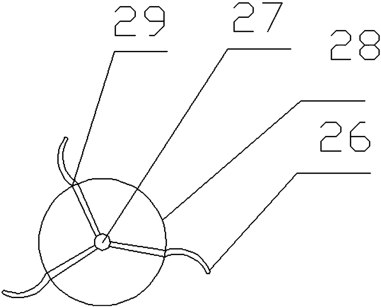
[0027] see Figure 1-3 , a medical waste treatment equipment, including a housing 1, a crushing device 12, a cleaning tank 10 and a heat melting furnace 21. A water tank 4 is fixedly installed at the bottom of the housing 1 , and a water inlet 3 is provided on the top of the side of the water tank 4 . Water tank 4 side bottoms are provided with water outlet 2, and water outlet 2 is provided with valve, and opening valve can discharge accumulated water in water tank 4 by water outlet 2. A water pipe 22 is arranged at the bottom of the water tank 4 , and the water pipe 22 communicates with the water pump 19 . Driven by the water pump 19 , the water in the water tank 4 is pumped into the water pipe 22 . The top of the housing 1 is provided with a feeding port 11, which extends to the inside of the housing 1. The setting of the feeding port 11 facilitates the entry of medical waste.

[0028] A horizontal first fixed plate 8 is fixed inside the housing 1, and a crushing device 12...

Embodiment 2

[0034] see Figure 4 , On the basis of Embodiment 1, the side of the water tank 4 is provided with a water viewing window 32, the water viewing window 32 is made of a transparent material, and the water in the water tank 4 can be observed through the water viewing window 32. Scale line 31 is engraved on the water viewing window 32, and the setting of scale line 31 can quantitatively measure the water yield in the water tank 4. The right end of the filter screen 15 is provided with a vibrator 33, the vibrator 33 is fixedly installed on the inner wall of the housing 1, the left end of the filter screen 15 is provided with a spring 34, and the spring 34 is fixed on the lower surface of the second fixed plate 14, Driven by the vibrator 33, the filter screen 15 vibrates with the internal materials at high frequency, which is conducive to the rapid dripping of water on the granular materials and the rolling of the granular materials.


PUM


Abstract

The invention relates to the field of waste treatment, in particular to a medical waste treatment device. The medical waste treatment device comprises a shell. A feeding port is formed in the top endof the shell. The feeding port communicates with a smashing device. A cleaning pool is fixedly installed at the lower end of the smashing device. Water spraying rows and a material collecting device are arranged in the cleaning pool. A filtering net is arranged below the cleaning pool. A gas spraying row and a hot melting furnace are arranged below the filtering net. By means of the medical wastetreatment device, water flow is used for transmission, and the energy utilization rate is increased. Ultrasonic cleaning is adopted, material cleaning is thorough, and the vibrating filtering net is used so that water disengaging and material conveying can be facilitated. Hot airflow is used for drying jittering materials, the drying effect is improved, and the work efficiency is improved. Hot airis used for preheating materials, and meanwhile a sterilizing and disinfecting effect is achieved. Materials enter the hot melting furnace to be melted, the materials can be thoroughly sterilized anddisinfected by the high temperature, and recycling standards are achieved. The medical waste treatment device is simple in structure, easy to operate, high in automation degree, high in sterilizing strength and capable of recycling waste materials.

Description

technical field [0001] The invention relates to the field of waste treatment, in particular to medical waste treatment equipment. Background technique [0002] During the operation of the hospital, a lot of medical waste will be generated. At present, many hospitals have sorted medical waste and carried out unified recycling and treatment. Due to the wide variety of viruses carried by medical waste, it is highly infectious and biologically toxic. If it is discharged and handled improperly, it will inevitably cause water, air, soil pollution and human health hazards. In particular, thorough disinfection and recycling are urgently needed. . Medical waste after thorough cleaning and disinfection can be recycled to realize waste reuse. [0003] Chinese patent (publication number: CN 105214125 A, publication date 2016.01.06) discloses a device for treating medical waste, including a feeding device, a disinfection tank, a high-temperature heating and control device, and a crush...

Claims


Application Information

Patent Timeline
Patent Type & Authority Applications(China)
IPC IPC(8): B09B3/00B09B5/00B08B3/12A61L11/00F26B21/00
CPCB09B3/0075A61L11/00F26B21/00B08B3/12B09B5/00B09B3/40
Inventor 宗磊
Owner 霸州市辉月网络技术有限公司
Learn More