
Hair dryer suitable for patients with shoulder discomfort

A hair dryer, uncomfortable technology, applied in the direction of application, washing hair or scalp devices, clothing, etc., can solve the problems of not being able to hair, not blowing the hair in place, and not being able to lift the arms above the top of the head or behind the head, so as to improve convenience Sexuality and the effect of broad market prospects

Inactive Publication Date: 2019-03-12
SHENZHEN LOTUT INNOVATION DESIGN CO LTD
View PDF7 Cites 0 Cited by
  • Summary
  • Abstract
  • Description
  • Claims
  • Application Information

AI Technical Summary

Problems solved by technology

However, when using an ordinary hair dryer, the hair on the back of the head is often not blown in place. Usually, the arms can be stretched to the back of the head to barely blow it. After that, you cannot use a hair dryer to blow the hair on the back of the head

Method used


Image

  • Hair dryer suitable for patients with shoulder discomfort
  • Hair dryer suitable for patients with shoulder discomfort
  • Hair dryer suitable for patients with shoulder discomfort

Examples


Embodiment 1

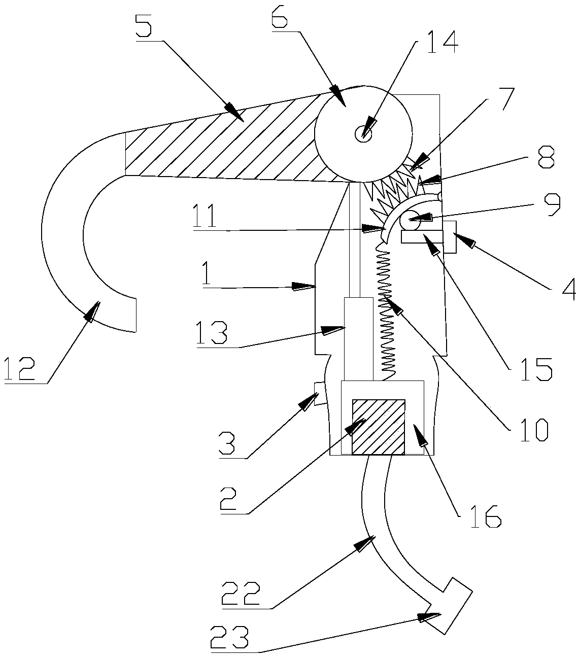
[0021] see Figure 1-3 , a hair dryer suitable for patients with shoulder discomfort, including a housing 1, a fan 2 and a sliding mechanism 4; ;

[0022] The upper end of the housing 1 is provided with a spherical hollow shell 6, and both sides of the spherical hollow shell 6 are provided with a rotating rod 14, the rotating rod 14 is connected to the inner side wall of the housing 1 through a bearing, and the rotating rod 14 and the bearing The spherical hollow shell 6 can be rotated, the outer side of the spherical hollow shell 6 communicates with the blowing pipe 5, and the other end of the blowing pipe 5 is threadedly connected to the arc-shaped connecting pipe 12;

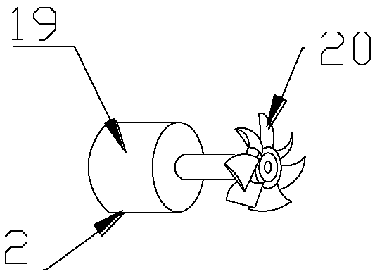
[0023] The outside of the fan 2 is provided with a thermal insulation box 16, which can reduce the influence of the external temperature environment on the fan 2 and improve safety. The fan 2 includes a motor 19 and fan blades 20. In this embodiment, the The motor 19 is a ZYT series micro motor of MAKA, the...

Embodiment 2

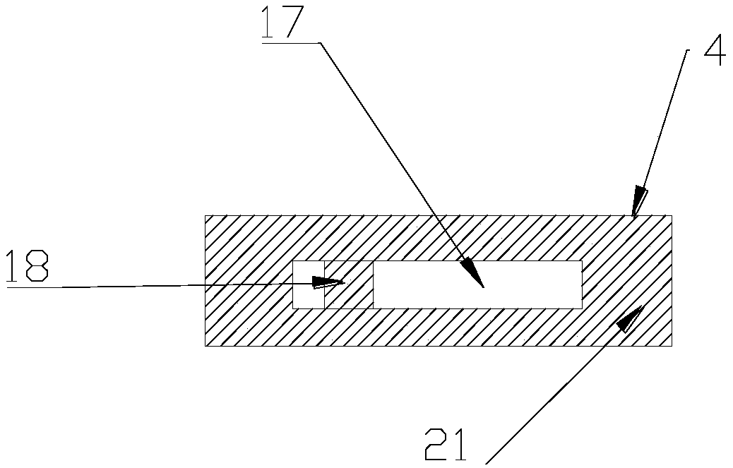
[0028] see Figure 2-4 , a hair dryer suitable for patients with shoulder discomfort, including a housing 1, a fan 2 and a sliding mechanism 4; The upper end of the housing 1 is provided with a spherical hollow shell 6, and both sides of the spherical hollow shell 6 are provided with a rotating rod 14, and the rotating rod 14 is connected to the inner side wall of the housing 1 through a bearing, and the rotating rod 14 and the The bearing can make the spherical hollow shell 6 rotate, and the outer side of the spherical hollow shell 6 communicates with the blowing pipe 5, and the outer side of the shell 1 is provided with a switch 3 for controlling the blower fan 2 and the electric heating element 13;

[0029] The outside of the fan 2 is provided with a thermal insulation box 16, which can reduce the influence of the external temperature environment on the fan 2 and improve safety. The fan 2 includes a motor 19 and fan blades 20. In this embodiment, the The motor 19 is a ZYT ...


PUM


Abstract

The invention discloses a hair dryer suitable for patients with shoulder discomfort. The hair dryer comprises a casing, a fan and a sliding mechanism; the upper end of the casing is provided with a spherical hollow shell, the outer side of the spherical hollow shell is communicated with an air blowing pipe, the outside of the fan is provided with a heat insulation box, an output end of the fan iscommunicated with an electric heating element, and the other end of the electric heating element is communicated with the spherical hollow shell; the sliding mechanism comprises a sliding mechanism main body and a sliding block, one end of the sliding block is connected with a connecting plate disposed in the casing, the upper end of the connecting plate is connected with a a ball, and an arc-shaped plate is arranged above the ball; the outer side of the arc-shaped plate is provided with a lower rack, and the right side of the spherical hollow shell is provided with an upper rack cooperating with the lower rack for use. The hair dryer can be applied to the patients with shoulder discomfort; through the cooperative use of the ball, the arc-shaped plate and the racks, uniform air blowing canbe conducted at various angles by flexibly controlling the sliding block, the hair dryer is convenient and flexible, a user has no need to lift the arms to the positions above the head or beyond thehead, and air can be blown to the hair on the back side of the head. The air dryer has a broad market prospect.

Description

technical field [0001] The invention relates to the field of household electrical appliances, in particular to a hair dryer suitable for patients with shoulder discomfort. Background technique [0002] Hair dryer is an article that is often used in people's daily life. It is mainly used for drying and shaping of hair, but it can also be used for local drying in laboratories, physiotherapy rooms, industrial production, and art. A hair dryer is usually composed of a set of heating wires and a high-speed small fan. When the power is turned on, the heating wires will generate heat, and the wind blown by the fan will become hot air after passing through the heating wires. However, when using an ordinary hair dryer, the hair on the back of the head is often not blown in place. Usually, the arms can be stretched to the back of the head to barely blow it. After that, you cannot use a hair dryer to blow the hair on the back of your head. Therefore, need to design a kind of hair dry...

Claims


Application Information

Patent Timeline
Patent Type & Authority Applications(China)
IPC IPC(8): A45D20/10A45D20/12
CPCA45D20/10A45D20/12
Inventor 沈周其他发明人请求不公开姓名
Owner SHENZHEN LOTUT INNOVATION DESIGN CO LTD
Learn More