
A thermal deformation error correction method for an optical camera in geostationary orbit

A technology of geostationary orbit and deformation error, applied in the field of space satellite positioning, to achieve the effect of improving the positioning accuracy on orbit, convenient use and reasonable design

Active Publication Date: 2022-02-18
SHANGHAI INST OF TECHNICAL PHYSICS - CHINESE ACAD OF SCI
View PDF0 Cites 0 Cited by
  • Summary
  • Abstract
  • Description
  • Claims
  • Application Information

AI Technical Summary

Problems solved by technology

[0009] The purpose of the present invention is to overcome the deficiencies of the prior art, to provide a thermal deformation error correction method for optical cameras in geostationary orbit, and to solve the problem of geometric positioning accuracy of high-orbit satellites

Method used


Image

  • A thermal deformation error correction method for an optical camera in geostationary orbit
  • A thermal deformation error correction method for an optical camera in geostationary orbit
  • A thermal deformation error correction method for an optical camera in geostationary orbit

Examples


Embodiment Construction

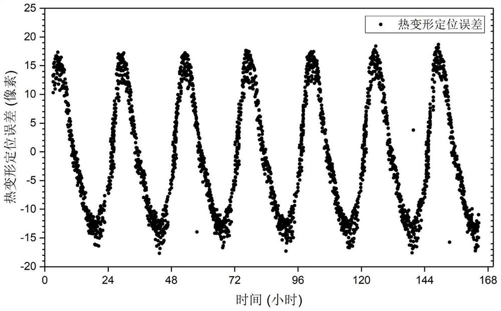
[0029] Taking the short-wave infrared data of a certain type of stationary orbit staring camera as an example below, select the thermal deformation positioning error data for 7 consecutive days, and further describe the specific embodiment of the present invention in conjunction with the accompanying drawings:

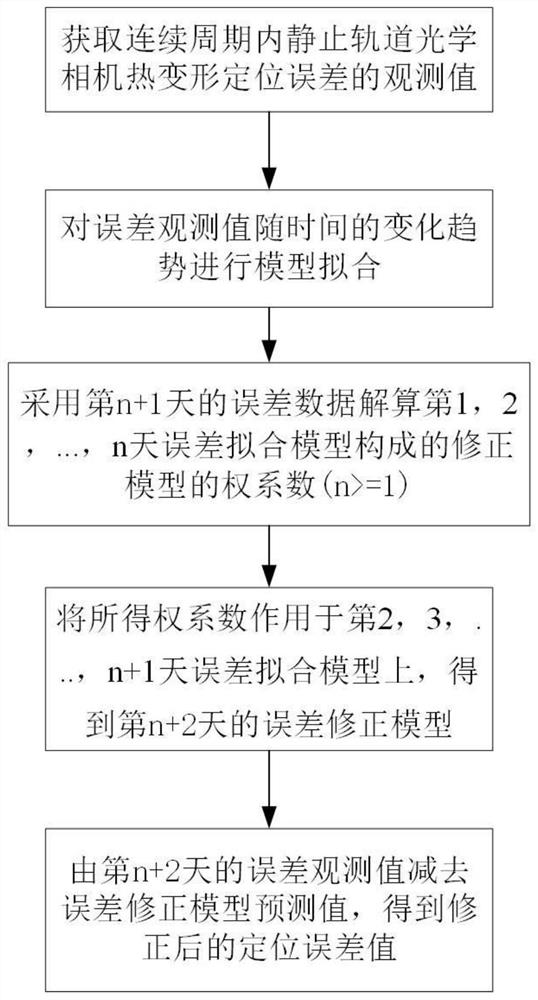
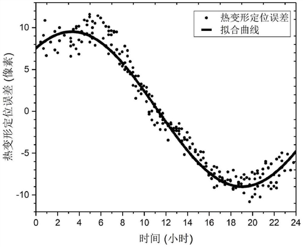
[0030] The present invention uses high-precision fitting of thermal deformation positioning error change law, and corrects the subsequent day's positioning error with a correction model formed by fitting models for n consecutive days. Here, n=3 is selected, and the Fourier series model is taken as the third order, and the method is described. It mainly includes the following steps:

[0031] (1) Through the geometric positioning model, the observation value of the thermal deformation positioning error of a certain type of geostationary optical camera in continuous periods is obtained; figure 2 Shown is the thermal deformation positioning error of this model of geostat...


PUM


Abstract

The invention discloses a method for correcting the thermal deformation error of an optical camera in geostationary orbit. The steps of the method are as follows: (1) obtaining the observation value of the thermal deformation positioning error of the optical camera in geostationary orbit in a continuous period; (3) use the error data of the n+1th day to solve the weight coefficient of the correction model formed by the error fitting model of the nth day; (4) (3) The obtained weight coefficient is applied to the error fitting model of the 2nd, 3rd, ..., n+1 days to obtain the error correction model of the n+2 day; (5) by the error fitting model of the n+2 day The error observation value is subtracted from the error correction model prediction value to obtain the corrected positioning error value. The invention can effectively correct the positioning error of the stationary orbit optical camera caused by thermal deformation, has the characteristics of reasonable design, high precision, low cost, convenient use, etc., and can be applied and promoted in the field of geometric positioning of high-precision remote sensing satellites.

Description

technical field [0001] The invention belongs to the technical field of space satellite positioning, and in particular relates to a positioning error correction method for space thermal deformation of an optical camera in geostationary orbit. Background technique [0002] Due to the characteristics of high time resolution, wide observation range and the ability to stare and image specific areas, geostationary orbit remote sensing cameras have been widely used in fields such as earth observation and space surveillance. Affected by the shock, vibration deformation and thermal deformation caused by the change of the incident angle of the sun when the satellite is launched, the geometric positioning model of the high-orbit remote sensing camera will change, thus affecting the final positioning accuracy of the camera. Therefore, it is often necessary to perform on-orbit calibration of the camera again. [0003] Affected by the altitude of the orbit, the temperature field around t...

Claims


Application Information

Patent Timeline
Patent Type & Authority Patents(China)
IPC IPC(8): G01C25/00
CPCG01C25/00
Inventor 陈凡胜孙胜利于清华林长青
Owner SHANGHAI INST OF TECHNICAL PHYSICS - CHINESE ACAD OF SCI
Learn More