Method for automatically detecting shielding state of laser receiving window

A technology of laser receiving and automatic detection, which is applied in the direction of weapon accessories, offensive equipment, training and matching components, etc., can solve the problems of increasing the training performance of the trainees, affecting the training effect of the actual combat training, and detrimental to the combat effectiveness of the troops. The effect of practical level

Inactive Publication Date: 2019-03-08
NO 60 RES INST OF GENERAL STAFF DEPT PLA
View PDF5 Cites 3 Cited by
  • Summary
  • Abstract
  • Description
  • Claims
  • Application Information

AI Technical Summary

Problems solved by technology

Therefore, if the laser receiving window of the simulator is blocked, the simulator will not receive the coded lasers emitted by other weapon simulators, resulting in the result that it cannot be damaged or destroyed, which seriously affects the training effect of actual combat training, and Encouraging the trainees to gain combat training results by cheating is not conducive to improving the combat effectiveness of the troops

Method used


Image

  • Method for automatically detecting shielding state of laser receiving window
  • Method for automatically detecting shielding state of laser receiving window
  • Method for automatically detecting shielding state of laser receiving window

Examples


Embodiment 1

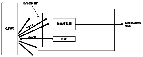
[0019] A laser receiver and a light source are installed in the laser receiving window of the weapon simulator. The light source and the laser receiver are on a horizontal line at different heights. The transmitting end of the light source and the receiving end of the laser receiver are both facing the laser receiving window.

[0020] The light source is connected to the coding device, and the coding device includes a modulating circuit module and a driving amplifying circuit module, the output end of the modulating circuit module is connected to the input end of the driving amplifying circuit module, and the output end of the driving amplifying circuit module is connected to the light source. The light beam is modulated and coded by the modulating circuit module to generate first coded information, and then amplified by the driving and amplifying circuit module to be emitted through the light source.

[0021] The wavelength of the light beam emitted by the light source is with...

Embodiment 2

[0025] A laser receiver and a light source are installed in the laser receiving window of the weapon simulator. The light source and the laser receiver are on a horizontal line at different heights. The transmitting end of the light source and the receiving end of the laser receiver are both facing the laser receiving window.

[0026] The light source is connected to the coding device, and the coding device includes a modulating circuit module and a driving amplifying circuit module, the output end of the modulating circuit module is connected to the input end of the driving amplifying circuit module, and the output end of the driving amplifying circuit module is connected to the light source. The light beam is modulated and coded by the modulating circuit module to generate first coded information, and then amplified by the driving and amplifying circuit module to be emitted through the light source.

[0027] The wavelength of the light beam emitted by the light source is with...


PUM


Abstract

The invention discloses a method for automatically detecting a shielding state of a laser receiving window, and relates to the technical field of real soldier combat training. A light source and a laser receiver are arranged in the laser receiving window. The light source is connected with an encoding device, and the encoding device is used for encoding light beams emitted by the light source to enable the light beams to contain first encoding information. The laser receiver is used for receiving laser beams emitted by a direct sight weapon simulator and the light beams emitted by the light source and analyzing the encoding information in the laser beams and the light beams. The laser receiver is connected with an upper computer. The light source is located at a different height from the laser receiver. If the laser receiver receives the light beams containing the first encoding information, it is determined that the laser receiving window is shielded; and if the laser receiver does not receive the light beams containing the first encoding information, it is determined that the laser receiving window is not shielded. The method can effectively recognize the shielding situation of the laser receiving window of the simulator in real soldier combat training.

Description

technical field [0001] The invention relates to the technical field of actual combat training, in particular to a method for automatically detecting the blocking state of a laser receiving window. Background technique [0002] At present, replacing live ammunition by firing lasers is an effective means for troops to conduct actual combat training. In actual combat training, various weapon simulators simulate the launch of ammunition by launching coded lasers containing weapon and ammunition information; various weapon simulations After the laser receiver installed on the device receives the coded laser beam containing weapon ammunition information, it can analyze the attack weapon ammunition information from the coded laser beam, and calculate the damage result according to the damage ability of the attack weapon ammunition and its own protection ability . Therefore, if the laser receiving window of the simulator is blocked, the simulator will not receive the coded lasers e...

Claims


Application Information

Patent Timeline
Patent Type & Authority Applications(China)
IPC IPC(8): F41A33/02
CPCF41A33/02
Inventor 陈峰万华
Owner NO 60 RES INST OF GENERAL STAFF DEPT PLA
Why Eureka
Try Eureka