Device for removing water from waste combustion tail gas

A waste combustion and exhaust gas technology, applied in the direction of combustion method, combustion type, deodorization, etc., can solve the problems of inability to separate liquids, doping harmful substances, environmental pollution, etc., and achieve the effect of preventing random discharge and good effect

Inactive Publication Date: 2019-03-08
广州顺途信息科技有限公司
View PDF8 Cites 1 Cited by
  • Summary
  • Abstract
  • Description
  • Claims
  • Application Information

AI Technical Summary

Problems solved by technology

[0002] Compared with landfill, composting and other waste treatment technologies, waste incineration has many advantages. Modern waste incineration plants can better realize waste reduction, harmlessness and resource utilization. With the acceleration of urbanization, waste With the increase of production and the improvement of calorific value, more and more cities in my country have adopted or plan to use incineration to...

Method used


Image

  • Device for removing water from waste combustion tail gas
  • Device for removing water from waste combustion tail gas
  • Device for removing water from waste combustion tail gas

Examples


Embodiment

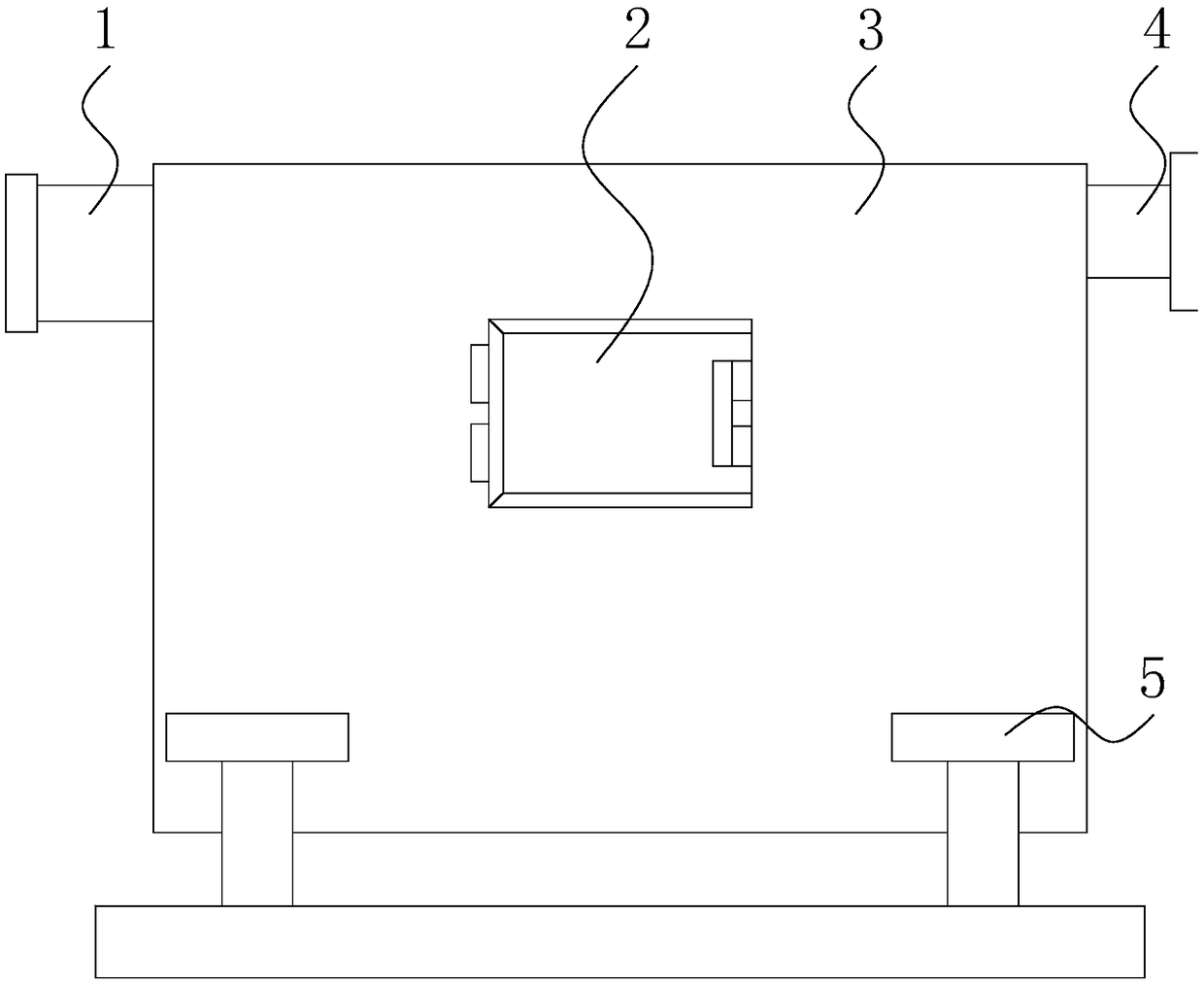
[0024] see Figure 1-Figure 5, the present invention provides a water removal device for waste combustion tail gas, the structure of which includes a purification outlet 1, a box door 2, a water removal host 3, an exhaust gas inlet 4, and a support base 5, and the purification outlet 1 is installed on the water removal host by embedding 3 on the left inner upper end, the box door 2 is hinged to the front surface of the water removal main machine 3, the left end of the exhaust gas inlet 4 is installed on the right inner upper end of the water removal main machine 3 by embedding, and the lower end of the water removal main machine 3 is welded to Support base 5 upper ends.

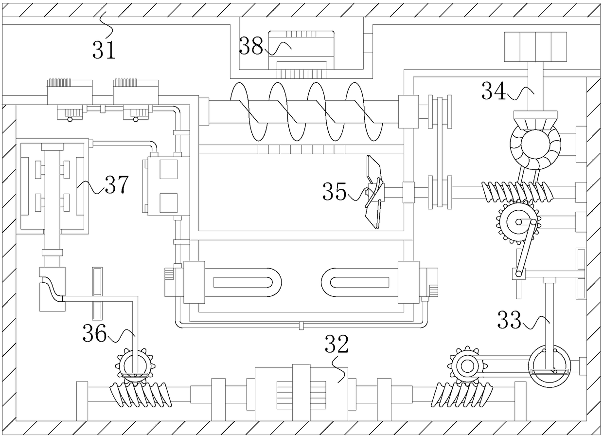
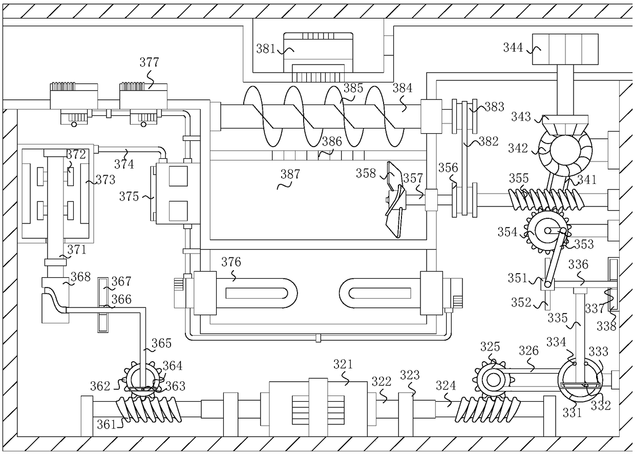
[0025] The main machine 3 for removing water comprises a main machine shell 31, a power mechanism 32, a driving mechanism 33, an air intake mechanism 34, a wind force mechanism 35, a transmission mechanism 36, a power supply mechanism 37, and a water collection mechanism 38. The outer surface of the lower end...


PUM


Abstract

The invention discloses a device for removing water from waste combustion tail gas. The device structurally comprises a purification outlet, a box door, a water removal main machine, a tail gas inletand supporting bases. The purification outlet is formed in the upper end inside the left side of the wat removal main machine in an embedding manner. The box door is hinged with the front surface of the water removal main machine. The left end of the tail gas inlet is arranged at the upper end inside the right side of the water removal main machine in an embedding manner. A driving mechanism is operated by opening a power mechanism, then a gas intake mechanism exhausts the tail gas into a water collection mechanism from the tail gas inlet; and through the compression work of the water collection mechanism and the action of a moisture removal box, the liquid is separated from the tail gas, and the liquid separation effect is better; then the liquid is removed through the work of a wind power mechanism; meanwhile a heater on a power supply mechanism carries out high-temperature treatment on the harmful substances in the liquid, the water removal effect is better, and the harmful substances are prevented from being discharged at will and polluting the environment; and the tail gas is exhausted again after the work of a negative ion generator to ensure that the air is not polluted.

Description

technical field [0001] The invention relates to the field of water removal devices for waste combustion tail gas, in particular to a water removal device for waste combustion tail gas. Background technique [0002] Compared with landfill, composting and other waste treatment technologies, waste incineration has many advantages. Modern waste incineration plants can better realize waste reduction, harmlessness and resource utilization. With the acceleration of urbanization, waste With the increase of production and the improvement of calorific value, more and more cities in my country have adopted or plan to use incineration to dispose of their domestic waste. However, the existing technology of dewatering device for waste incineration tail gas cannot perform well in the process of dewatering. The liquid in the tail gas is separated, and the post-treatment of the separated liquid is insufficient. The liquid in the tail gas is generally doped with harmful substances. If the liqui...

Claims


Application Information

Patent Timeline
IPC IPC(8): F23G5/44F23J15/02A61L9/22
CPCA61L9/22F23G5/44F23J15/02
Inventor 刘施文
Owner 广州顺途信息科技有限公司
Why Eureka
Try Eureka