A self-balancing throttle valve

A throttling valve and self-balancing technology, applied in balancing valves, valve devices, safety valves, etc., can solve problems such as poor adjustment accuracy, unstable throttle valve outlet pressure, and inflexible installation

Active Publication Date: 2019-12-13
JIANGSU CUMT DAZHENG SURFACE ENG TECH
View PDF3 Cites 0 Cited by
  • Summary
  • Abstract
  • Description
  • Claims
  • Application Information

AI Technical Summary

Problems solved by technology

[0007] The purpose of the embodiments of the present invention is to provide a self-balancing throttle valve to solve the problems of unstable outlet pressure, poor adjustment accuracy and inflexible installation of the throttle valve in the prior art

Method used


Image

  • A self-balancing throttle valve
  • A self-balancing throttle valve
  • A self-balancing throttle valve

Examples


Embodiment 1

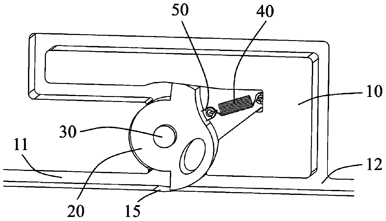
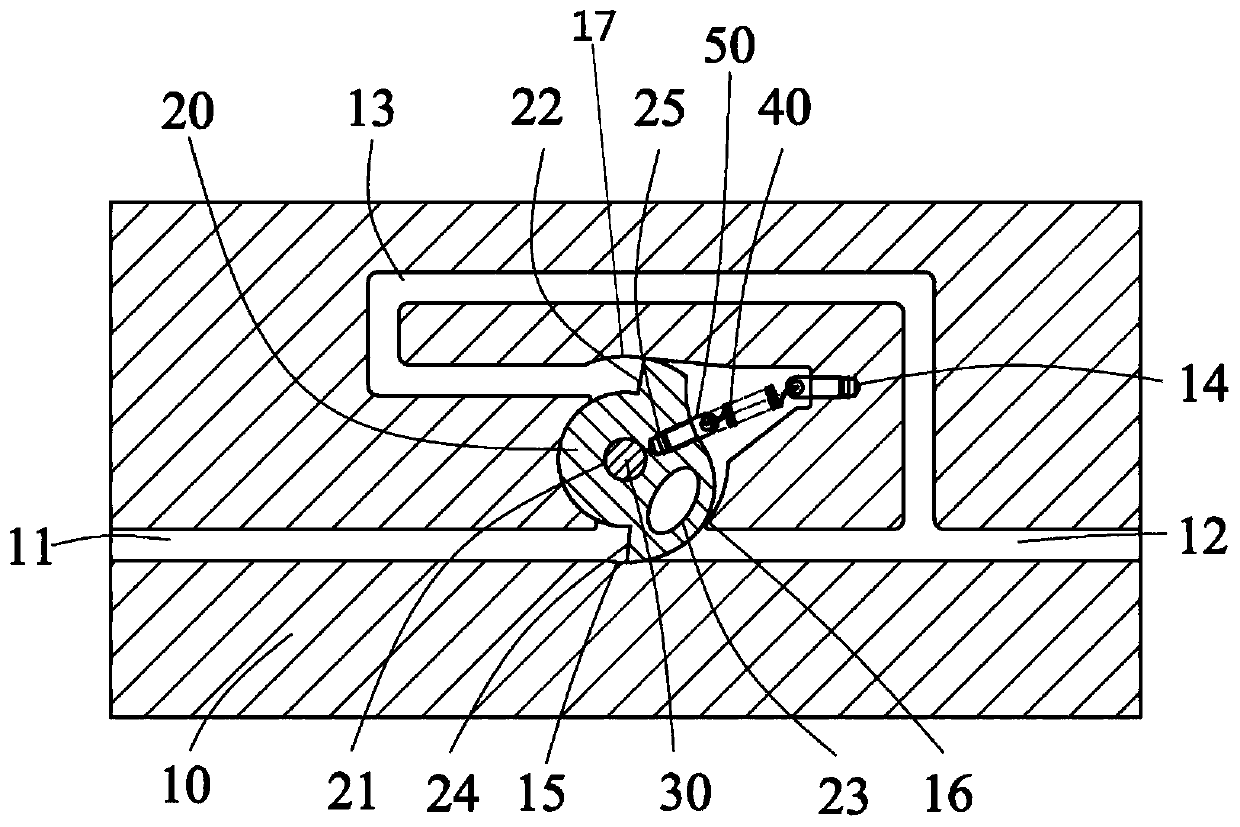
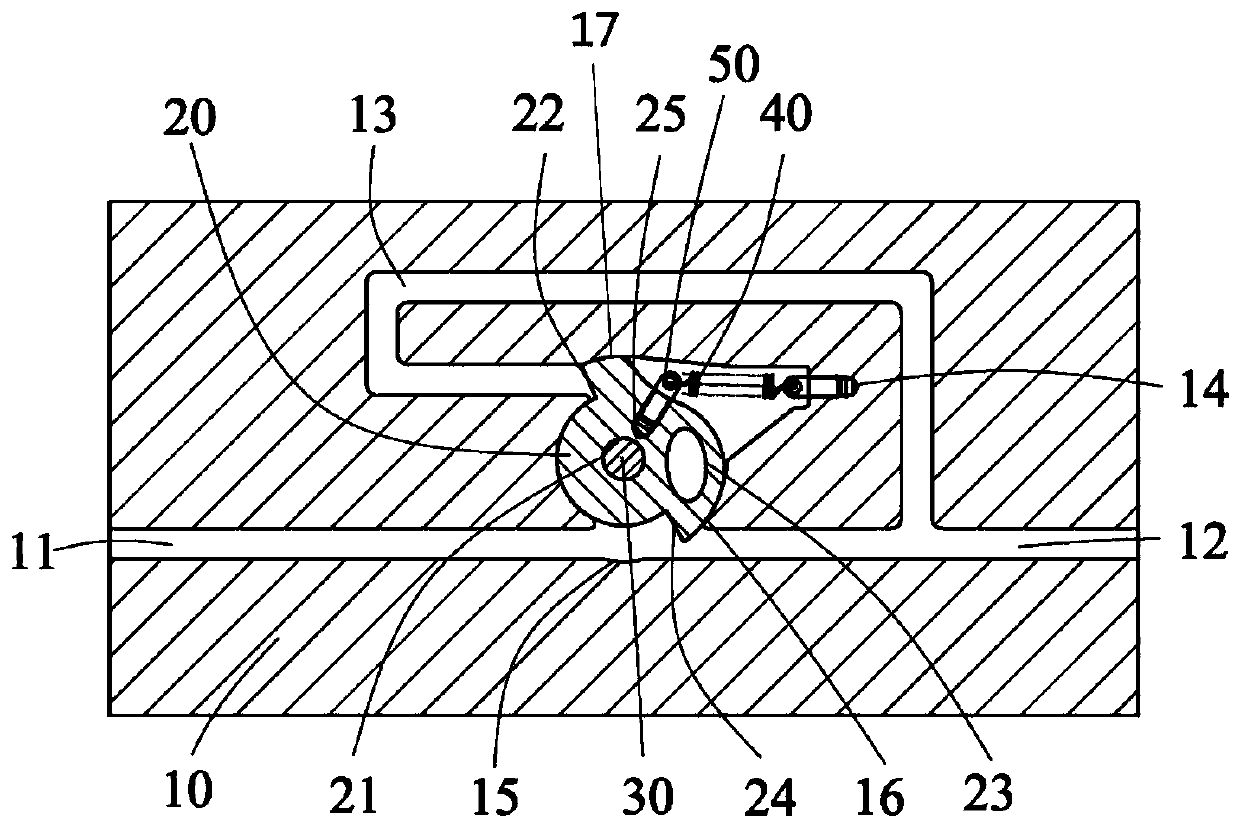
[0026] This embodiment provides a throttle valve. refer to figure 1 , figure 2 , image 3 , Figure 4 , The throttle valve provided in this embodiment includes a valve body 10 , a valve core 20 , a rotating shaft 30 , an elastic member 40 , a first screw 50 , and a second screw 14 .

[0027] The elastic member 40 is a spring, which specifically can be a tension spring, a compression spring, or a torsion spring.

[0028] The valve body 10 is provided with a main pipeline inlet 11 , a main pipeline outlet 12 and a fluid outlet feedback pipeline 13 ; the main pipeline inlet 11 and the main pipeline outlet 12 are located at two ends of a main pipeline.

[0029] One end of the fluid outlet feedback pipeline 13 is located on the branch of the main pipeline outlet 12 , and the other end faces the outlet pressure feedback surface 22 of the valve core 20 . Therefore, the fluid outlet feedback pipe 13 can introduce the outlet fluid (or gas) to the outlet pressure feedback acting s...


PUM


Abstract

The embodiment of the invention discloses a self-balancing throttling valve. The throttling valve comprises a valve body, the valve body comprises a valve element, a rotating shaft, a main pipeline inlet, a main pipeline outlet and a fluid outlet feedback pipeline are arranged in the valve body, wherein the main pipeline inlet and the main pipeline outlet are located at the two ends of one main pipeline; the valve element is located on the main pipeline, and is eccentrically installed on the valve body through the rotating shaft; one end of an elastic part is fixed on the valve element, and the other end of the valve element is fixed on the valve body; the valve element comprises an inlet pressure acting surface, the inlet pressure acting surface faces the main pipeline inlet; and one endof the fluid outlet feedback pipeline is located on a branch pipeline at the outlet of the main pipeline, and the other end faces the outlet pressure feedback action surface of the valve element. According to the throttling valve provided by the embodiment, the opening degree of the valve element can be automatically adjusted according to the pressure of the outlet fluid, the valve element works in a rotating mode, and can be installed at any working angle.

Description

technical field [0001] The invention relates to the technical field of fluid flow control, in particular to a self-balancing throttle valve. Background technique [0002] The main cable of the suspension bridge is wound with multiple steel wires or steel bars, and there will inevitably be gaps between the steel wires or steel bars. Suspension bridges are generally erected along the coast, so they will be exposed to an environment with high relative humidity all year round. At this time, the gaps between the steel wires will accelerate the corrosion of the steel wires or steel bars and shorten the service life of the bridge. [0003] Corrosion protection of the main cable steel wire of the bridge is an effective way to prolong the life of the bridge. The effect of passive protection is limited. In recent years, active protection measures have gradually become the main method of bridge steel cable protection. A common practice in active protection is to pass dry air into the...

Claims


Application Information

Patent Timeline
Patent Type & Authority Patents(China)
IPC IPC(8): F16K17/04
CPCF16K17/04
Inventor 程帅奇索双富王洋
Owner JIANGSU CUMT DAZHENG SURFACE ENG TECH
Why Eureka
Try Eureka