A new hob for shield machine

A shield machine, a new type of technology, applied in mining equipment, tunnels, earthwork drilling and mining, etc., can solve the problems of cutter body wear and scrap, cumbersome replacement process, short service life, etc., to achieve convenient installation and replacement, simple replacement process, The effect of long service life

Inactive Publication Date: 2020-08-14
浙江硕阳机械股份有限公司
View PDF7 Cites 0 Cited by
  • Summary
  • Abstract
  • Description
  • Claims
  • Application Information

AI Technical Summary

Problems solved by technology

[0003] 1. The cutter ring on the hob is easy to wear and deform. If the cutter ring wears to a certain extent or is deformed and damaged, the cutter ring needs to be replaced. The hob used in the current shield machine adopts interference fit for the installation of the cutter ring and the cutter body. Replace the cutter ring A variety of supporting facilities need to be used in the process, and the replacement process is cumbersome
[0004] 2. When the hob is cutting rock and soil, the cutter ring will crush and crush the rock and soil. The mechanical heat generated during the rolling and crushing process will form a gap between the cutter ring and the cutter body, and a gap will be formed between the cutter body and the cutter ring. Movement, the ability to drive the cutter body to rotate itself is weakened, the relative sliding between the cutter ring and the cutter body, the cutter ring is eccentrically worn, cracked, and falls off, the cutter body is worn out and scrapped, and the service life is short

Method used


Image

  • A new hob for shield machine
  • A new hob for shield machine
  • A new hob for shield machine

Examples


Embodiment Construction

[0027] The following will clearly and completely describe the technical solutions in the embodiments of the present invention with reference to the accompanying drawings in the embodiments of the present invention. Obviously, the described embodiments are only some, not all, embodiments of the present invention. Based on the embodiments of the present invention, all other embodiments obtained by persons of ordinary skill in the art without making creative efforts belong to the protection scope of the present invention.

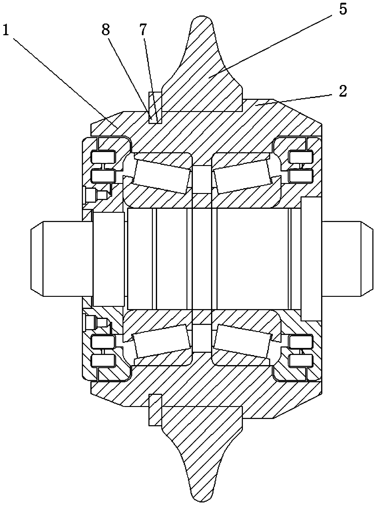
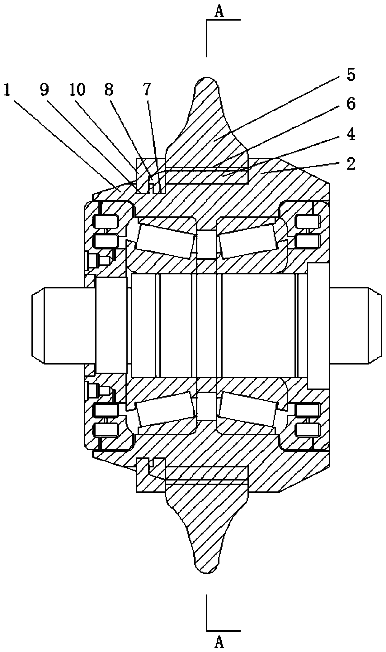
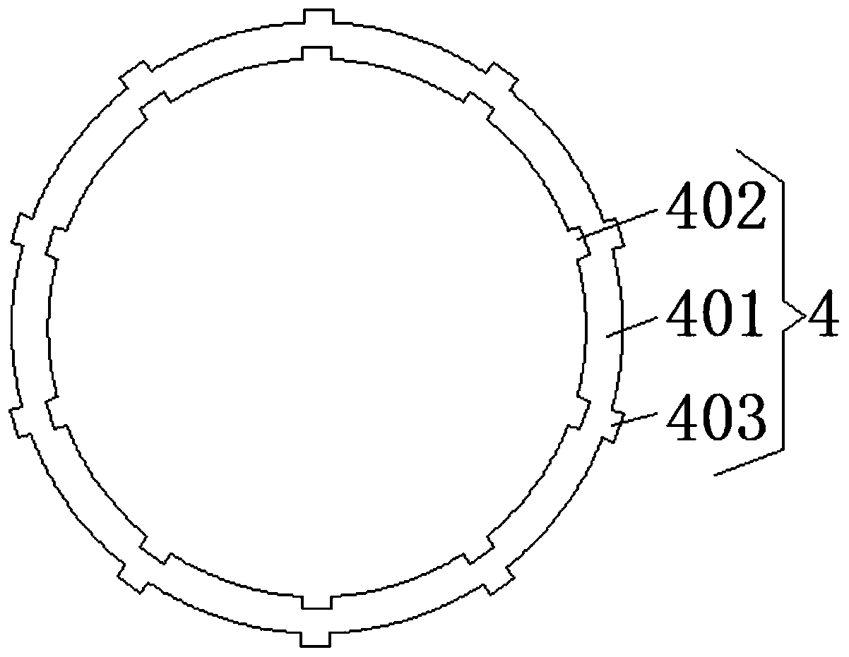
[0028] see Figure 1-9 , a new hob for a shield machine, comprising a cutter body 1, the outside of the cutter body 1 is provided with a boss 2, and the outside of the cutter body 1 is provided with an anti-aliasing tooth 3 on the left side of the boss 2 , the outside of the cutter body 1 is provided with an expansion member 4, the outside of the expansion member 4 is provided with a cutter ring 5, the inner surface of the cutter body 1 is provided with a limi...


PUM


Abstract

The invention relates to the technical field of shield machine parts, and discloses a novel hob for a shield machine. The hob comprises a hob body, a boss is arranged on the outer part of the hob body, channeling preventing teeth which are located on the left side of the boss are arranged on the outer part of the hob body, an expansion piece is arranged on the outer part of the hob body in a sleeving mode, and a hob ring is arranged on the outer part of the expansion piece in a sleeving mode; and a limiting groove is formed in the inner surface of the hob body, a fixing groove which is locatedon the left side of the expansion piece is formed in the outer part of the hob body, and a fixing piece is arranged on the outer part of the fixing groove. The expansion piece and the hob body are arranged in a matched mode, the expansion piece is arranged on the outer part of the hob body in a sleeving mode conveniently, the fixing groove is matched with the fixing piece to fix the expansion piece on the outer part of the hob body, the top surface of the fixing piece is arranged obliquely to guide the hob ring, and the hob ring is arranged on the outer part of the expansion piece in a sleeving mode conveniently; and the limiting groove is matched with a limiting piece to fix the hob ring, the hob ring is installed and replaced conveniently, the replacing process is simple, and additionalcorollary equipment is not needed.

Description

technical field [0001] The invention relates to the technical field of shield machine accessories, in particular to a new hob for a shield machine. Background technique [0002] The shield machine is a kind of tunnel boring machine that uses the shield method to excavate tunnels. It is widely used in urban underground engineering and subway tunnel excavation operations. It is mainly composed of shields, propulsion systems, and excavation systems. The excavation system includes power systems, The cutterhead and hob, etc. The hob is mainly composed of cutter body, cutter shaft, bearing, sealing ring, end cover, lubricating oil and cutter ring. The rock mass is rolled, Broken to complete the excavation. But the existing hob still has the following problems in use: [0003] 1. The cutter ring on the hob is easy to wear and deform. If the cutter ring wears to a certain extent or is deformed and damaged, the cutter ring needs to be replaced. The hob used in the current shield ma...

Claims


Application Information

Patent Timeline
Patent Type & Authority Patents(China)
IPC IPC(8): E21D9/08
CPCE21D9/08
Inventor 不公告发明人
Owner 浙江硕阳机械股份有限公司
Why Eureka
Try Eureka