Automatic door derail-preventing rail

An automatic door, derailment prevention technology, applied in door/window accessories, switches with brakes, wing parts, etc., can solve the problems of frame friction or collision, slider detachment, jamming, etc., to speed up startup , the effect of reducing vibration, reducing collision and friction

Inactive Publication Date: 2019-03-08
安徽晶鹏智能装备科技有限公司
View PDF0 Cites 2 Cited by
  • Summary
  • Abstract
  • Description
  • Claims
  • Application Information

AI Technical Summary

Problems solved by technology

[0002] Automatic door refers to the control unit that recognizes the action of people approaching the door as the door opening signal, opens the door through the drive system, automatically closes the door after the person leaves, and realizes the control system for the process of opening and closing. Automatic doors and non-automatic doors The door moves in the same way, and the movement of the rollers or sliders in the track drives the displacement of the main body of the door; the existing automatic door track has certain disadvantages in use, and it is easy to cause the slider to slide after a long time of use or after being subjected to external collisions. It breaks away from the guide rail and causes jamming. At the same time, when the automatic door is received in the frame, there will be a friction or collision with the frame, which will easily cause damage to both sides and bring certain adverse effects during use. Therefore, We propose an automatic door anti-derailment track

Method used


Image

  • Automatic door derail-preventing rail
  • Automatic door derail-preventing rail
  • Automatic door derail-preventing rail

Examples


Embodiment Construction

[0016] In order to make the technical means, creative features, goals and effects achieved by the present invention easy to understand, the present invention will be further described below in conjunction with specific embodiments.

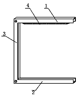
[0017] Such as Figure 1-3 As shown, an automatic door anti-derailment track includes an upper track 1, a lower track 2 and a storage frame 3. The upper track 1, the lower track 2 and the storage frame 3 are fixedly connected by rivets, and the lower end surface of the upper track 1 is riveted with an extended guard Plate 4 increases the limit width of the upper rail 1, and the interior of the storage frame 3 is welded in turn from top to bottom with No. 1 channel steel 5 and No. 2 channel steel 6, and both No. 1 channel steel 5 and No. 2 channel steel 6 run through Three sets of springs 7 are installed; a guide rail 8 is welded at the inner middle position of the lower track 2, and the upper end surface of the guide rail 8 is provided with an ant...


PUM


Abstract

The invention discloses an automatic door derail-preventing rail. The automatic door derail-preventing rail comprises an upper rail, a lower rail and a storage frame. The upper rail and the storage frame are fixedly connected through rivets, and the lower rail and the storage frame are fixedly connected through rivets. A lengthened protective plate is connected with the lower end face of the upperrail in a riveting mode, and first channel steel and second channel steel are welded inside the storage frame in sequence from top to bottom. According to the automatic door derail-preventing rail, due to the fact that a falling-preventing arc-shaped face, auxiliary rails and steel tooth grooves are arranged and mutually embedded, the area of contact between the falling-preventing arc-shaped faceand an inner groove of a sliding block is increased through the arc-shaped face, widened chamfers prevent the sliding block from being inclined, the chamfers cooperate with protrusions of the slidingblock to enable the sliding block to move in sliding grooves, and the phenomenon that the position of the sliding block on a guide rail deviates is avoided on the premise that the movement speed is not affected. Due to the fact that the steel tooth grooves and springs are arranged, the purpose of fixing is achieved, the shock in the contact process is reduced, and the automatic door derail-preventing rail is firmer, is suitable for different working conditions and has the better application prospect.

Description

technical field [0001] The invention relates to the field of automatic doors, in particular to an anti-derailing track for automatic doors. Background technique [0002] Automatic door refers to the control unit that recognizes the action of people approaching the door as the door opening signal, opens the door through the drive system, automatically closes the door after the person leaves, and realizes the control system for the process of opening and closing. Automatic doors and non-automatic doors The door moves in the same way, and the movement of the rollers or sliders in the track drives the displacement of the main body of the door; the existing automatic door track has certain disadvantages in use, and it is easy to cause the slider to slide after a long time of use or after being subjected to external collisions. It breaks away from the guide rail and causes jamming. At the same time, when the automatic door is received in the frame, there will be a friction or coll...

Claims


Application Information

Patent Timeline
IPC IPC(8): E05D15/06E05F5/08E05C17/02
CPCE05D15/0686E05C17/02E05D15/0691E05F5/003E05F5/08
Inventor 胡四九
Owner 安徽晶鹏智能装备科技有限公司
Why Eureka
Try Eureka