
Drainage pipeline construction component and method

A technology for drainage pipelines and components, which is applied to drainage pipeline construction components and their construction fields, can solve the problems of inability to take into account positioning stability and free positioning, and high stability of positioning degrees of freedom, so as to improve construction reliability, reduce construction damage, and improve reliability. The effect of high degree of freedom

Inactive Publication Date: 2019-03-08
温州金德市政建设有限公司
View PDF10 Cites 2 Cited by
  • Summary
  • Abstract
  • Description
  • Claims
  • Application Information

AI Technical Summary

Problems solved by technology

[0005] The first object of the present invention is to provide a drainage pipe construction component, which solves the problem that positioning stability and free positioning cannot be taken into account when positioning support, and achieves the advantages of high positioning freedom and high stability after positioning

Method used


Image

  • Drainage pipeline construction component and method
  • Drainage pipeline construction component and method
  • Drainage pipeline construction component and method

Examples


Embodiment 1

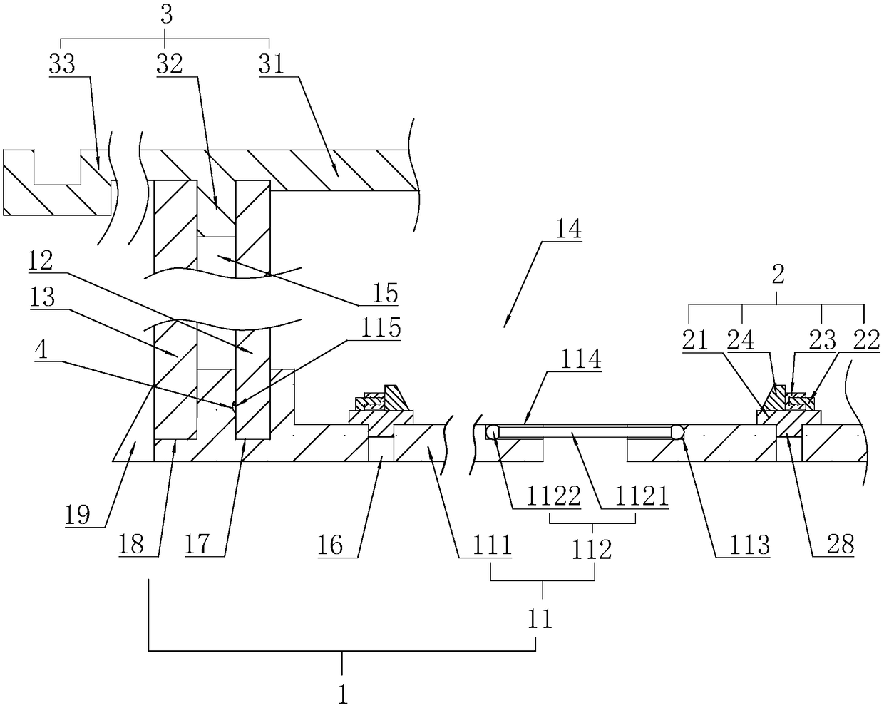
[0045] Example 1: Sewer pipe construction components such as figure 1 As shown, it includes an external frame 1 , a base assembly 2 and a cover assembly 3 .

[0046] The external frame 1 includes a base plate 11, two inner plates 12 and two outer plates 13; the two inner plates 12 and the base plate 11 are combined to form a mounting groove 14, and a fixing groove 15 is formed between the inner plate 12 and the outer plate 13. On the base plate 11 A positioning groove 16 is provided through it.

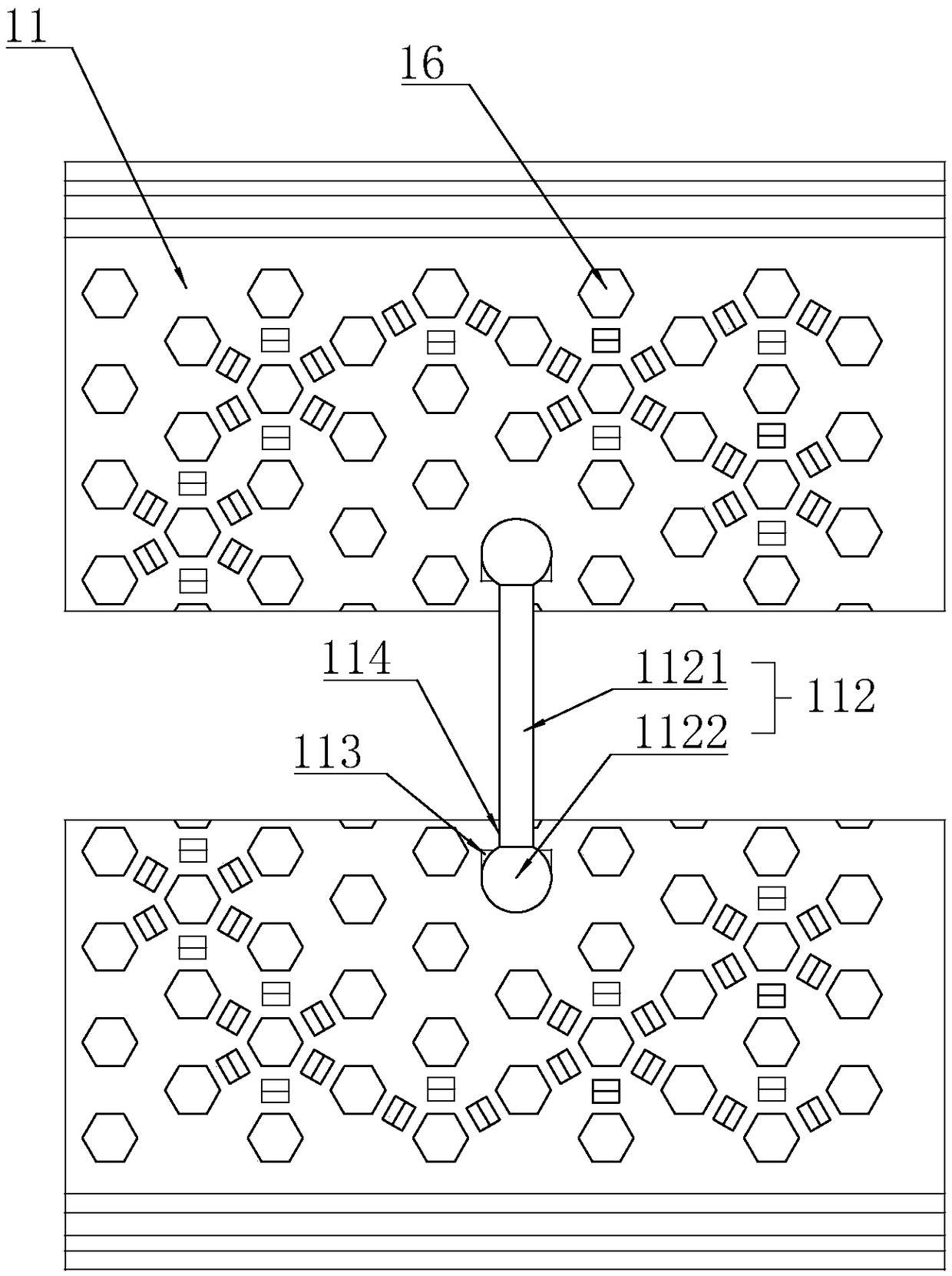
[0047] refer to figure 1 and figure 2 The bottom plate 11 includes two seat plates 111 and a connector 112 connecting the seat plates 111. The connector 112 includes a rod portion 1121 and a spherical end 1122 whose diameter is larger than the rod portion 1121. The seat plate 111 is provided with a socket for the spherical end 1122 to insert. The limiting groove 113 connected to it and the via hole 114 through which the rod portion 1121 passes, the limiting groove 113 runs through...

Embodiment 2

[0052] Embodiment 2, the construction that adopts construction assembly comprises the following steps:

[0053] Step S1 After the excavation of the trench is completed, clean the bottom of the trench according to the designed elevation of the trench bottom, and sprinkle water in a smooth manner;

[0054] Step S2 laying the trench, laying gravel on the bottom of the trench, and vibrating it to keep the surface smooth;

[0055] Step S3 Install the external frame 1, lay the seat plate 111 symmetrically on the surface of the cushion layer and connect it to the bottom plate 11 with the connector 112; connect the outer plate 13 with the outer embedded groove 18 of the bottom plate 11, and keep it vertical all the time, and then Fill concrete between the outer panel 13 and the inner wall of the groove; then abut the inner panel 12 with the embedded groove 17;

[0056] Step S4: Install the bottom assembly 2, install the bottom assembly 2 at the corresponding position through the posi...


PUM


Abstract

The invention relates to a drainage pipeline construction component and method. The drainage pipeline construction component comprises an external frame, a cushion component and a covering component.The external frame encloses a mounting channel having an opening and at least two fixing channels distributed on two sides of the mounting channel in spaced manner; the bottom of the mounting channelis provided with a plurality of positioning channels; the cushion component is arranged in the mounting channel, and the bottom of the cushion component is provided with positioning protrusions matingwith the positioning grooves; the covering component includes a cover plate and a fixing connector fixed to the bottom of the cover plate and embedded in a fixing channel. The drainage pipeline construction component has the advantages that stable positioning supports are freely formed according to different application sites and structures, protection is provided around, construction reliabilityand early and late protective effects are effectively improved, construction damage is decreased, and the service life of a pipeline is extended.

Description

technical field [0001] The invention relates to the technical field of municipal pipeline engineering, in particular to a drainage pipeline construction component and a construction method thereof. Background technique [0002] In the construction process of municipal rainwater and sewage pipelines in cities and towns, formwork is often required to form foundation support or side support. [0003] The Chinese patent whose authorized notification number is CN203096897U discloses a drainage pipeline construction component. The drainage pipeline construction component, including the pipeline, is characterized in that: the pipeline is arranged on two pipeline pads, and the pipeline stabilizers are respectively fixedly connected with the pipeline stabilizers above the pipeline cushions, and the pipeline stabilizers are respectively tangent to the pipeline, and the pipeline is stable Lifting holes are respectively arranged on the body. [0004] The disadvantage of the existing t...

Claims


Application Information

Patent Timeline
IPC IPC(8): E03F3/02E03F3/04E03F3/06
CPCE03F3/02E03F3/04E03F3/06
Inventor 黄启盛黄立兴周思思章少央翁传恳
Owner 温州金德市政建设有限公司
Learn More