Eureka AIR delivers breakthrough ideas for toughest innovation challenges, trusted by R&D personnel around the world.

Heavy falling weight deflectometer bearing disc self-adapting pavement device

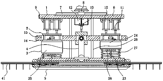
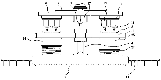
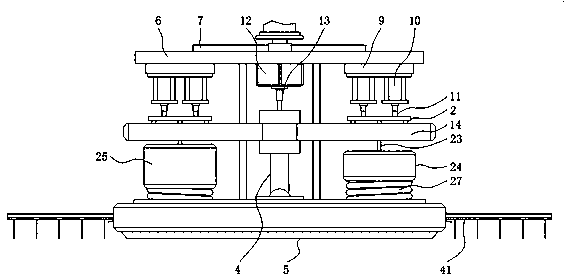
A drop-weight deflection meter and bearing plate technology, which is applied to roads, roads, road repairs, etc., can solve problems such as data errors in deflection basins, inconformity with impact conditions, and inability to guarantee vertical downward action of impact forces. Achieve good structural elasticity, ensure structural firmness and structural strength

Pending Publication Date: 2019-03-08
南京侨睿交通技术有限公司
View PDF0 Cites 2 Cited by
  • Summary
  • Abstract
  • Description
  • Claims
  • Application Information

AI Technical Summary

Problems solved by technology

[0003] During the use of modern drop weight deflectometers, when faced with the influence of road slope factors, the reaction action or offset method is not ideal. When the heavy drop weight deflectometer is placed on the road, Due to the slope of some tested road surfaces, it is impossible to ensure that the impact force of the hammer body acts on the tested road surface vertically. Under normal circumstances, the impact force direction of the hammer body is perpendicular to the road surface, but this does not meet the requirements of driving vehicles. The impact of its gravity on the road surface when driving on a sloped road surface leads to a large error in the deflection basin data obtained by the final drop weight deflection meter compared with the real situation.

Method used


Image

  • Heavy falling weight deflectometer bearing disc self-adapting pavement device
  • Heavy falling weight deflectometer bearing disc self-adapting pavement device
  • Heavy falling weight deflectometer bearing disc self-adapting pavement device

Examples


Embodiment Construction

[0030] The following will clearly and completely describe the technical solutions in the embodiments of the present invention with reference to the accompanying drawings in the embodiments of the present invention. Obviously, the described embodiments are only some, not all, embodiments of the present invention.

[0031] In the description of the present invention, unless otherwise stated, the meaning of "plurality" is two or more; the terms "upper", "lower", "left", "right", "inner", "outer" , "front end", "rear end", "head", "tail", etc. indicate the orientation or positional relationship based on the orientation or positional relationship shown in the drawings, and are only for the convenience of describing the present invention and simplifying the description, rather than Nothing indicating or implying that a referenced device or element must have a particular orientation, be constructed, and operate in a particular orientation should therefore not be construed as limiting ...


PUM


Abstract

The invention discloses a heavy falling weight deflectometer bearing disc self-adapting pavement device, and relates to the technical field of a falling weight deflectometer. The heavy falling weightdeflectometer bearing disc self-adapting pavement device concretely comprises a bearing main body, frame carrying mechanisms, a falling weight mechanism, a self regulation mechanism and a base, wherein the frame carrying mechanisms are arranged at two sides of the inner side of the bearing main body; the falling weight mechanism is arranged under the frame carrying mechanisms; the self regulationmechanism is arranged at the middle lower part of the bearing main body; the base is arranged under the self regulation mechanism; the bearing main body consists of an upper lifting disc and a lower lifting disc; the falling weight mechanism comprises first heavy hammers and second heavy hammers; the first heavy hammers are respectively arranged at the right corner of the front side of the upper part and the left corner of the back side of the upper part of the base. The heavy falling weight deflectometer bearing disc self-adapting pavement device has the advantages that through the arrangement of the self regulation mechanism, the device can be automatically regulated; according to the pavement gradient, the impact direction on the pavement always maintains the vertical direction, and isnot in a vertical state with the pavement.

Description

technical field [0001] The invention relates to the technical field of drop weight deflection gauges, in particular to a heavy-duty drop weight deflection gauge load plate self-adaptive road surface device. Background technique [0002] The drop weight deflection tester (or heavy-duty drop weight deflection tester) is a pulse dynamic deflection tester, which has the advantages of no damage, fast measurement speed, high precision, etc., and well simulates the driving load. The test result is The scope of application of deflection basin data is mainly in the aspect of road maintenance and management. The working principle of the drop hammer deflection meter is that by lifting a heavy hammer of a certain mass from a hydraulic transmission device to a certain height and then falling freely, the impact force acts on The bearing plate is transmitted to the road surface, thereby applying a pulse load to the road surface, resulting in instantaneous deformation of the road surface su...

Claims


Application Information

Patent Timeline
IPC IPC(8): E01C23/01
CPCE01C23/01
Inventor 何正东
Owner 南京侨睿交通技术有限公司
Why Eureka
Eureka Blog
Learn More