Semi-automatic deburring device

A deburring and semi-automatic technology, which is applied in the field of ring gear processing, can solve the problems of potential safety hazards, low work efficiency, and high labor intensity, and achieve the effects of saving gear deburring time, low cost, and reducing labor intensity

Pending Publication Date: 2019-03-08
GETRAG JIANGXI TRANSMISSION
View PDF0 Cites 0 Cited by
  • Summary
  • Abstract
  • Description
  • Claims
  • Application Information

AI Technical Summary

Problems solved by technology

The removal of burrs is very important. The deburring of burrs will scratch the tooth surface, reduce the fatigue life of the ring gear, and pose a safety hazard.
The conventional method of deburring the ring gear in the industry is to use an ordinary lathe to deburr. Iron filings will splash during the operation, and the working environment is harsh, the work efficiency is low, the labor intensity is high, and there are potential safety hazards.

Method used


Image

  • Semi-automatic deburring device
  • Semi-automatic deburring device

Examples


Embodiment Construction

[0015] The invention will be described in detail below in conjunction with the accompanying drawings and embodiments.

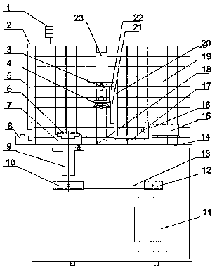
[0016] Such as Figures 1 to 2 As shown, the present invention proposes a semi-automatic deburring equipment, including a workbench 14, a connection seat 9 is provided under one end of the workbench 14, a large pulley 10 is arranged and connected to the bottom of the connection seat 9, and a belt 13 is installed on the outside of the large pulley 10 , the other end of the belt 13 is connected to the small pulley 12, the lower end of the small pulley 12 is connected to the drive shaft of the motor 11, a fixed tooling 7 is fixed directly above the connecting seat 9, the fixed tooling 7 fixes the ring gear 6, and the fixed tooling 7 It is connected with the ring gear 6 model, and the upper end of the workbench 14 is provided with a cylinder fixing plate 16 and a horizontal guide rail 18. The upper end of the slider 17 is provided with a Z-shaped connecting plat...


PUM


Abstract

The invention discloses a semi-automatic deburring device. The semi-automatic deburring device comprises a workbench, a connecting seat, a large belt wheel, a belt, a small belt wheel, a motor and a fixing tool, and further comprises a gear ring, a transversely arranged air cylinder, a transversely arranged sliding block, a transversely arranged guide rail, a Z-shaped connecting plate, a longitudinally arranged guide rail, a longitudinally arranged sliding block, a U-shaped connecting plate, a deburring cutter, a protective net, a grating, a switch button and other components. The semi-automatic deburring device is mainly characterized in that the motor provides power, the power is transmitted to the gear ring through the small belt wheel, the belt, the large belt wheel, a connecting seat,the fixing tool and other transmission devices, then the gear ring is driven to rotate, a PLC program controls the cutter to do axial and radial movement and act on the end surface of the gear ring,and finally, the deburring effect is achieved; and the operation is simple and convenient, and the manufacturing cost is low, the deburring time of the gear is saved, the working efficiency is improved, the labor intensity is reduced, and meanwhile, the effects of being safe and reliable are achieved.

Description

technical field [0001] The invention relates to the field of ring gear processing, in particular to a semi-automatic deburring device. Background technique [0002] Burrs refer to the generation of grain shear slip and plastic deformation under the action of cutting force during metal processing, which causes the material to be squeezed and torn, resulting in irregular metal parts such as various sharp corners and burrs at the transition of the workpiece surface. . [0003] The tooth shape of the ring gear is processed by gear shaping. The main cutting motion of gear shaping processing is that the gear shaping cutter is driven by the main shaft of the gear shaping machine to reciprocate up and down perpendicular to the end face of the gear. Therefore, after the ring gear undergoes gear shaping, it will Circle the lower end face, resulting in burrs. The removal of burrs is very important. The deburring of burrs will scratch the tooth surface, reduce the fatigue life of the ...

Claims


Application Information

Patent Timeline
IPC IPC(8): B23D79/00
CPCB23D79/00
Inventor 邹恒文赵梦天余涛刘雪勇饶绍丁郗正寒程卫国谢伟华
Owner GETRAG JIANGXI TRANSMISSION
Why Eureka
Try Eureka