U-shaped housing and cover concept for plate fin heat exchangers

A technology for heat exchangers and shells, applied in the field of shell configuration of heat exchangers, can solve the problems of joint leakage, increase manufacturing and assembly costs, and complex shells, and achieve minimal leakage, manufacturing and assembly costs. minimized effect

Inactive Publication Date: 2019-03-05
HANON SYST
View PDF5 Cites 4 Cited by
  • Summary
  • Abstract
  • Description
  • Claims
  • Application Information

AI Technical Summary

Problems solved by technology

Disadvantageously, however, the housing may be complex or formed from multiple parts, for example three or more
Numerous parts add to manufacturing and assembly costs
In addition, the multiple components are prone to leaks at the joints of the multiple components forming the housing

Method used


Image

  • U-shaped housing and cover concept for plate fin heat exchangers
  • U-shaped housing and cover concept for plate fin heat exchangers
  • U-shaped housing and cover concept for plate fin heat exchangers

Examples


Embodiment Construction

[0015] The following detailed description and drawings describe and illustrate various embodiments of the invention. The description and drawings are intended to enable a person skilled in the art to make and use the invention and are not intended to limit the scope of the invention in any way. With respect to the disclosed methods, the steps presented are exemplary in nature, and thus, the order of the steps is not required or critical. As used herein, the term "substantially" means "mainly but not completely" or "approximately" as will be recognized by those skilled in the art from the specification and drawings.

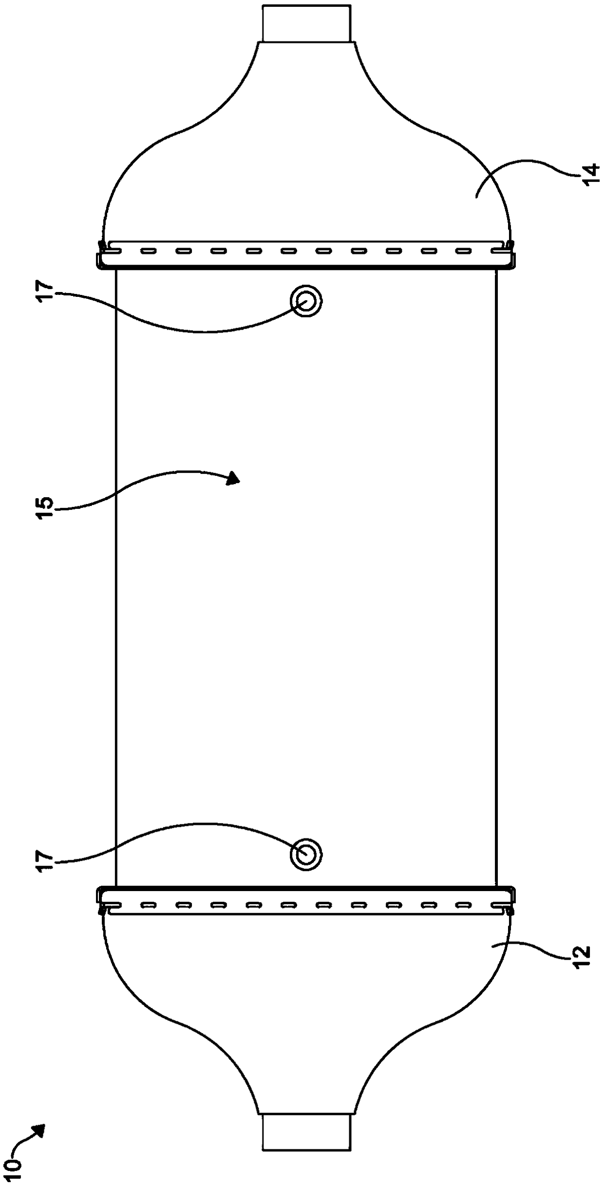
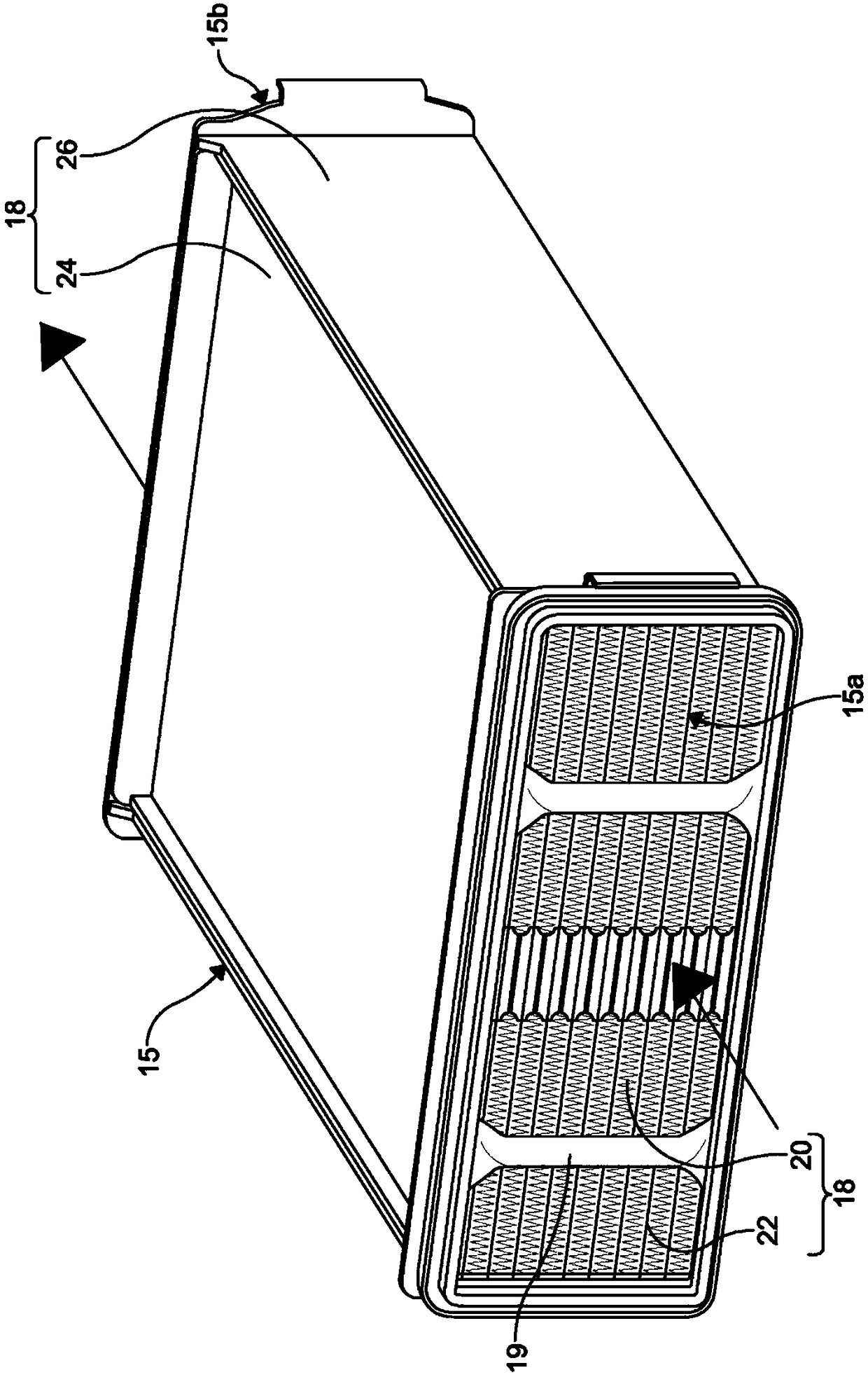
[0016] figure 1 A heat exchanger 10 according to an embodiment of the present disclosure is shown. As shown, the heat exchanger 10 is configured as an intercooler, such as, for example, a water-cooled charge air cooler. However, it will be appreciated that heat exchanger 10 may be configured as any type of heat exchanger commonly used in vehicle systems, such a...


PUM


Abstract

The invention provides a housing for a heat exchanger, a core assembly for a heat exchanger and a heat exchanger for a vehicle. The housing for a heat exchanger includes a first housing portion havingand a second housing portion. The first housing portion has a U-shaped cross-section. The second housing portion cooperates with the first housing portion to define a chamber. The chamber receives aheat exchange assembly. The second housing portion is configured as a plate.

Description

technical field [0001] The present invention relates to a heat exchanger for a vehicle, and more particularly, to a housing configuration for the heat exchanger. Background technique [0002] It is well known that it is desirable for the air entering a vehicle engine to be cooled, especially after leaving a turbocharger or supercharger, since cooler air will have an increased density to maximize the efficiency of the engine. Cooling of the air may also facilitate engine management and eliminate pre-detonation of air and fuel prior to timing spark ignition in some cases. In addition, cooling the air prevents excessive wear or thermal damage to the engine block of the engine. [0003] Heat exchangers such as water-cooled charge air coolers (WCACs) may be used in vehicles to cool air that has been compressed by a turbocharger or supercharger before entering the engine. Typically, for applications with specific requirements such as space constraints in a vehicle, for example, ...

Claims


Application Information

Patent Timeline
Patent Type & Authority Applications(China)
IPC IPC(8): F28F9/00F28F9/02
CPCF28F9/001F28F9/02F02B29/0462F28D9/0037F28D2021/0082F28D2021/0089F28D2021/0094Y02T10/12F28D9/0031F28F9/0219F28F21/065F28F21/084F28D9/0006
Inventor 亚历克斯·麦克旦尼尔利奥·绍姆豪斯特约恩·斯坦斯菲尔德史蒂文·乔伊斯
Owner HANON SYST
Why Eureka
Try Eureka