Winding position identification device and method for wireless power transmission based on pre-excitation magnetic field

A technology of wireless energy transmission and identification method, which is applied in the field of wireless energy transmission winding position identification device, can solve the problems of low precision and poor versatility, and achieve the effects of solving poor versatility, reducing the detection area, and improving detection efficiency

Active Publication Date: 2020-11-24
NANJING UNIV OF AERONAUTICS & ASTRONAUTICS +1
View PDF12 Cites 0 Cited by
  • Summary
  • Abstract
  • Description
  • Claims
  • Application Information

AI Technical Summary

Problems solved by technology

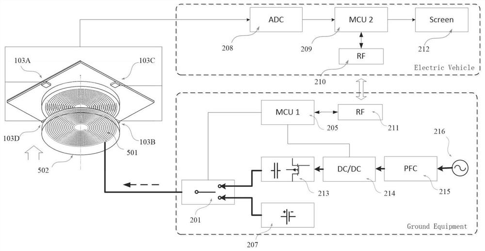
[0008] The purpose of the present invention is to address the deficiencies of the above-mentioned background technology, provide a wireless power transmission winding position identification device and method based on a pre-excitation magnetic field, use the published general law of magnetic field distribution and the method for determining key parameters of magnetic field characteristics, and then combine The magnetic field information and its position information detected by the magnetic sensor can realize the accurate identification of dislocation information, which solves the problems of poor versatility and low precision of traditional positioning methods

Method used


Image

  • Winding position identification device and method for wireless power transmission based on pre-excitation magnetic field
  • Winding position identification device and method for wireless power transmission based on pre-excitation magnetic field
  • Winding position identification device and method for wireless power transmission based on pre-excitation magnetic field

Examples


Embodiment Construction

[0046] The technical solution of the invention will be described in detail below in conjunction with the accompanying drawings. This invention may be embodied in many different forms and should not be construed as limited to the exemplary embodiments set forth herein.

[0047] For ease of description, spatially relative terms such as "upper," "lower," "left," and "right" may be used herein to describe the relationship of one element or feature relative to another element or feature shown in the figures. It will be understood that the spatial terms are intended to encompass different orientations of the device in use or operation in addition to the orientation depicted in the figures. For example, if the device in the figures is turned over, elements described as "below" other elements or features would then be oriented "above" the other elements or features. Thus, the exemplary term "below" can encompass both an orientation of above and below, the device can be otherwise orie...


PUM


Abstract

The invention discloses a wireless power transmission winding position identification device and method based on a pre-excitation magnetic field, and belongs to the technical field of wireless power supply. The wireless power transmission winding position identification device comprises a pre-excitation winding, a magnetic sensor, a controller and a pre-excitation power supply. The winding position identification method comprises the following steps of applying a pre-excitation current to the pre-excitation winding, constructing the pre-excitation magnetic field, and detecting the magnetic field sensing intensity in the position of the sensor through the magnetic sensor on the other side. According to a distribution function of the pre-excitation magnetic field disclosed by the invention,the distance between the sensor and the central axis of the pre-excitation side winding is judged, and the dislocation coordinates are determined through a multi-sensor geometric relation. Based on the magnetic field "zero crossing point" characteristic point, the magnetic field distribution rule of the excitation windings with different magnetic structures and different parameters can be automatically determined, and then the relative position coordinates of the pre-excitation winding are calculated, thereby providing in-place information and accurate dislocation position information for automatic parking, automatic charging of an electric automobile and automatic adjustment and compensation of wireless power supply.

Description

technical field [0001] The invention discloses a wireless power transmission winding position identification device and method based on a pre-excitation magnetic field, and belongs to the technical field of wireless power supply. Background technique [0002] Wireless power supply technology has been applied to fields such as electric vehicles, automated guided vehicles (AGV, Automated Guided Vehicle), drones, and autonomous driving, especially where automatic charging is required. Compared with contact power supply, wireless power supply has the advantages of safety, flexibility, no spark, less maintenance, mobility and easy automatic charging. [0003] Since the primary and secondary sides of the wireless power supply system can be separated, it is inevitable that there will be various situations such as air gap changes, horizontal and vertical dislocations, etc., which will cause the coupling coefficient of the non-contact transformer and the self-inductance of the primar...

Claims


Application Information

Patent Timeline
Patent Type & Authority Patents(China)
IPC IPC(8): H02J50/90
CPCH02J50/90
Inventor 张斌陈乾宏温振霖徐立刚耿玉川高伟赵静任小永张之梁
Owner NANJING UNIV OF AERONAUTICS & ASTRONAUTICS
Why Eureka
Try Eureka