Single-end travelling wave range finding method for common-tower double-loop T-joint power transmission line

A transmission line, single-ended traveling wave technology, applied in the direction of measuring electricity, measuring devices, measuring electrical variables, etc., can solve the problems of heavy load, difficulty in obtaining fault information, and high transmission power, so as to reduce difficulty and facilitate reliable distance measurement Effect

Inactive Publication Date: 2019-03-01
KUNMING UNIV OF SCI & TECH
View PDF6 Cites 1 Cited by
  • Summary
  • Abstract
  • Description
  • Claims
  • Application Information

AI Technical Summary

Problems solved by technology

At the same time, the double-circuit T-shaped transmission line has the characteristics of high transmission power and heavy load. Once the line fails, it may cause large-scale power outages.
Moreover, most of the fault branch judgment and distance measurement of double-circuit T-connected transmission lines now use the fault information of the two ends and the three ends of the measurement end, but it is very difficult to obtain the fault information of the two ends and three ends of the transmission line at the same time scale. Difficult and takes time

Method used


Image

  • Single-end travelling wave range finding method for common-tower double-loop T-joint power transmission line
  • Single-end travelling wave range finding method for common-tower double-loop T-joint power transmission line
  • Single-end travelling wave range finding method for common-tower double-loop T-joint power transmission line

Examples


Embodiment 1

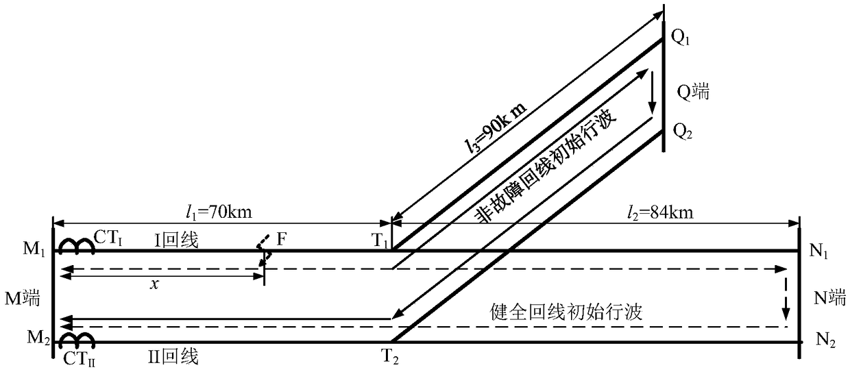
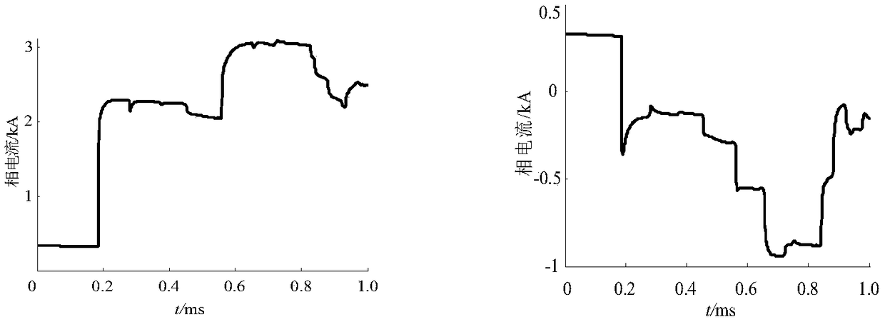
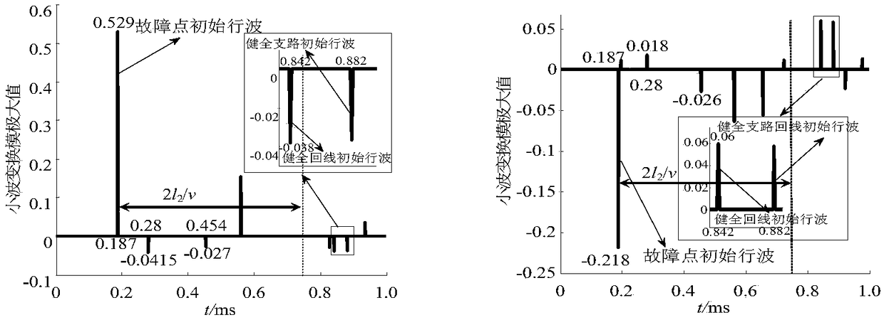
[0050] Embodiment 1: as Figure 1-3 As shown, the simulation model of a 110kV AC double-circuit T-connection line on the same tower is as follows figure 1 Shown; Its line parameter is as follows: MT branch line road length is 70km, NT branch line road length is 84km, QT branch line road length is 90km, namely (l 1 2 3 ). Fault location: The I circuit line is 56km away from the M terminal and a fault occurs. The sampling frequency is 1MHz.

[0051] (1) Obtain CT according to the first step to the second step in the manual I and CT II The wavelet transform modulus maximum value of the first traveling wave, it can be easily seen from the above figure that the I loop line a-phase current modulus maximum value is greater than the II loop line a-phase current modulus maximum value, so it can be judged that the fault line is I back to the transmission line.

[0052] (2) According to the second step in the manual, the initial traveling wave head of the fault point reaches the me...

Embodiment 2

[0055] Embodiment 2: as figure 1 , 4 As shown in -5, the simulation model of a 110kV AC double-circuit T-connection line on the same tower is as follows figure 1 Shown; Its line parameter is as follows: MT branch line road length is 70km, NT branch line road length is 84km, QT branch line road length is 90km, namely (l 1 2 3 ). Fault location: The NT branch of the I-circuit line is 94km away from the M terminal. The sampling frequency is 1MHz.

[0056] (1) Obtain CT according to the first step to the second step in the manual I and CT II The wavelet transform modulus maximum value of the first traveling wave, it can be easily seen from the above figure that the I loop line a-phase current modulus maximum value is greater than the II loop line a-phase current modulus maximum value, so it can be judged that the fault line is I back to the transmission line.

[0057] (2) According to the second step in the manual, the initial traveling wave head of the fault point reaches ...

Embodiment 3

[0060] Embodiment 3: as figure 1 , 6 As shown in -7, the simulation model of a 110kV AC double-circuit T-connection line on the same tower is as follows figure 1 Shown; Its line parameter is as follows: MT branch line road length is 70km, NT branch line road length is 84km, QT branch line road length is 90km, namely (l 1 2 3 ). Fault location: The QT branch of the I circuit line is faulted 100km away from the M terminal. The sampling frequency is 1MHz.

[0061] (1) Obtain CT according to the first step to the second step in the manual I and CT II The wavelet transform modulus maximum value of the first traveling wave, it can be easily seen from the above figure that the I loop line a-phase current modulus maximum value is greater than the II loop line a-phase current modulus maximum value, so it can be judged that the fault line is I back to the transmission line.

[0062] (2) According to the second step in the manual, the initial traveling wave head of the fault point...


PUM


Abstract

The invention relates to a single-end travelling wave range finding method for a common-tower double-loop T-joint power transmission line, and belongs to the technical field of power transmission linefault positioning. The method comprises the steps: reading current travelling waves of two loop lines measured by a measurement-end high-speed collection device; employing a third spline wavelet function for detecting and verifying the obtained current travelling waves, comparing the maximum values of the current travelling waves of the measurement ends of the two loop lines, and extracting the traveling waves in a time window min {[t1, t1 + 2l2 / v], [t1, t1 + 2l3 / v]}, judging the amplitudes and extreme values of the traveling waves of the two loop lines in the time window, judging whetherthere is a healthy loop line initial traveling wave or not: determining that a fault happens to an MT segment or a QT segment if there is no healthy loop line initial traveling wave, determining thatthere is definitely a traveling wave reflecting the total length NT of the line in the neighbourhood of the moment of t1+2l2 / v if a fault happens to a QT branch circuit, or else determining that thefault happens to an MT branch circuit; determining that the fault happens to the NT segment or a QT segment if there is the fault; determining that there is definitely a traveling wave reflecting thetotal length QT of the line in the neighbourhood at the moment of t1+2l3 / v if the fault happens to the NT segment, or else determining that the fault happens to the QT branch circuit, and calculatinga fault distance through a single-end traveling wave range-finding formula.

Description

technical field [0001] The invention relates to a single-end traveling wave ranging method for a double-circuit T-connected transmission line on the same tower, and belongs to the technical field of transmission line fault location. Background technique [0002] With the rapid development of my country's power grid, more and more double-circuit T-connection transmission lines on the same tower appear in the high-voltage power grid. Double-circuit transmission lines on the same tower have the advantages of large transmission capacity, narrow outlet corridor, and small footprint. They are widely used in high-voltage transmission networks. Double-circuit transmission lines on the same tower are connected to each other to form a double-circuit T-shaped transmission line. The double-circuit T-shaped transmission line has simple wiring and fast construction speed, which can effectively reduce equipment investment. At the same time, the double-circuit T-shaped transmission line ha...

Claims


Application Information

Patent Timeline
IPC IPC(8): G01R31/08
CPCG01R31/085G01R31/088
Inventor 束洪春蔡梦娟宋晶田鑫萃魏泰鸣
Owner KUNMING UNIV OF SCI & TECH
Why Eureka
Try Eureka