Waste heat annealing system suitable for total oxygen kiln furnace

A waste heat annealing and kiln furnace technology, which is applied in furnaces, waste heat treatment, furnace components, etc., can solve the problems of high temperature of exhausted smoke and waste heat that cannot be used beneficially

Pending Publication Date: 2019-03-01
李福全
View PDF0 Cites 0 Cited by
  • Summary
  • Abstract
  • Description
  • Claims
  • Application Information

AI Technical Summary

Problems solved by technology

[0004] The present invention aims at the existing problem of reducing the emission in glass manufacturing, and uses more oxygen kilns instead of the existing horseshoe flame kilns. The design of the whole oxygen kilns has less regenerators, and the outlet temperature of the flue reaches 1200 degrees. , there are problems that the temperature of the exhausted dust is too high and the waste heat cannot be used beneficially, and a waste heat annealing system suitable for an all-oxygen pit furnace is provided

Method used


Image

  • Waste heat annealing system suitable for total oxygen kiln furnace
  • Waste heat annealing system suitable for total oxygen kiln furnace
  • Waste heat annealing system suitable for total oxygen kiln furnace

Examples


Embodiment 1

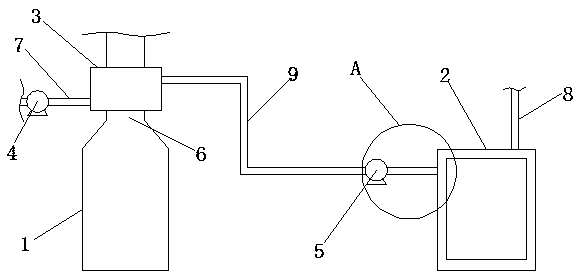
[0029] Such as figure 1 As shown, the waste heat annealing system suitable for an all-oxygen furnace includes an all-oxygen furnace 1 and an annealing furnace 2. The top of the all-oxygen furnace 1 is provided with a smoke outlet channel 6, wherein a heat exchanger 3 is arranged on the smoke outlet channel 6. The air inlet of the heat exchanger 3 is connected with the air inlet pipe 7, the air outlet of the heat exchanger 3 is connected with one end of the heat preservation pipe 9, the other end of the heat preservation pipe 9 is connected with the air inlet of the annealing furnace 2, and the air outlet of the annealing furnace 2 is connected with the air outlet of the annealing furnace 2. The air duct 8 is connected, the air inlet duct 7 is provided with an induced draft fan 4, and the thermal insulation pipe 9 is provided with a heat-regulating fan 5.

[0030] In use, a heat exchanger is installed on the smoke outlet channel of the all-oxygen kiln furnace. The clean air fro...

Embodiment 2

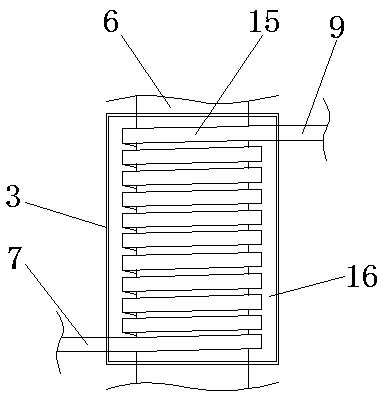
[0033] Based on Example 1, such as image 3 As shown, the heat exchanger 3 includes a shell, a heat exchange chamber 16 and a heat exchange tube 15, and the two ends of the heat exchange tube 15 communicate with the air inlet tube 7 and the heat preservation tube 9 respectively. The smoke outlet channel 6 passes through the shell of the heat exchanger 3 , and the heat exchange tube 15 is wound on a section of the smoke outlet channel 6 located in the heat exchange chamber 16 .

[0034] In use, the smoke outlet channel is passed through the shell of the heat exchanger, and the heat exchange tube is wound on the smoke outlet channel, which can increase the contact area between the smoke outlet channel and the heat exchange tube, thereby improving the heat exchange effect.

Embodiment 3

[0036] Based on Example 1, such as Figure 4 As shown, the heat exchanger 3 includes a shell, a heat exchange chamber 16 and a heat exchange tube 15, and the two ends of the heat exchange tube 15 communicate with the air inlet tube 7 and the heat preservation tube 9 respectively. The smoke outlet channel 6 is connected to the bottom of the shell of the heat exchanger 3 and communicated with the heat exchange chamber 16. The top of the shell of the heat exchanger 3 is provided with a smoke exhaust pipe 17 communicated with the heat exchange chamber 16. The heat exchange pipe 15 is in the shape of a snake. The two ends of the heat exchange tube 15 are located on both sides of the shell of the heat exchanger 3 respectively.

[0037] This embodiment provides another heat exchanger structure, which connects the smoke outlet channel to the bottom of the heat exchanger shell, so that the high-temperature gas in the smoke outlet channel can fill the heat exchange chamber, which is con...


PUM


Abstract

The invention relates to the field of waste heat utilization, in particular to a waste heat annealing system suitable for a total oxygen kiln furnace. The waste heat annealing system comprises a totaloxygen kiln furnace and an annealing furnace, wherein the top of the total oxygen kiln furnace is provided with a smoke discharging channel, the smoke discharging channel is provided with a heat exchanger, an air inlet of the heat exchanger is communicated with an air inlet pipe, an air outlet of the heat exchanger is communicated with one end of a heat insulation pipe, the other end of the heatinsulation pipe is connected with an air inlet of the annealing furnace, an air outlet of the annealing furnace is connected with an air outlet pipe, an induced draft fan is arranged on the air inletpipe, and a heat-adjusting fan is arranged on the heat insulation pipe. The problem is solved that for decreasing the emissions produced in glass manufacture, the total oxygen kiln furnace is usuallyused for replacing an existing horse shoe flame kiln furnace, a heat accumulation chamber is omitted by adopting the design of the total oxygen kiln furnace, the temperature of a flue outlet reaches 120 DEG C and accordingly the temperature of discharged smoke dust is excessively high and waste heat cannot be effectively utilized.

Description

technical field [0001] The invention relates to the field of waste heat utilization, in particular to a waste heat annealing system suitable for an all-oxygen kiln furnace. Background technique [0002] At present, there are only two methods of annealing in a gas-fired annealing furnace and electric heating in the annealing process of international and domestic glass products. The annealing process is essential, otherwise it will cause bursting in use, resulting in unsafe and substandard quality. Whether it is gas heating annealing or electric heating annealing, it will cause energy consumption and increase of product cost. [0003] In order to reduce the emission problem in glass manufacturing, the oxygen kiln furnace is used instead of the existing horseshoe furnace furnace. The design of the all oxygen kiln has less regenerators, and the flue outlet temperature reaches 1200 degrees, and there is a temperature of exhaust smoke Problems that are too high and waste heat ca...

Claims


Application Information

Patent Timeline
IPC IPC(8): C03B25/00F27B17/00F27D17/00
CPCF27B17/00F27D17/004C03B25/00Y02P10/25
Inventor 李福全李景雯牛童王基威
Owner 李福全
Why Eureka
Try Eureka