Clamping device of numerical control tool chuck

A tool chuck and clamping device technology, which is applied in positioning devices, clamping, manufacturing tools, etc., can solve the problems of easy damage, collision deformation, and lack of CNC tool chucks, etc., to achieve good clamping effect, Not easy to be damaged by collision, good stability

Pending Publication Date: 2019-03-01
南京雄豹精密机械有限公司
View PDF0 Cites 0 Cited by
  • Summary
  • Abstract
  • Description
  • Claims
  • Application Information

AI Technical Summary

Problems solved by technology

[0003] The purpose of the present invention is to provide a clamping device for CNC tool holders, which solves the technical problem of the lack of proprietary clamping devices for CNC tool holders in the prior art, resulting in easy damage or collision deformation of the disassembled CNC tool holders

Method used


Image

  • Clamping device of numerical control tool chuck
  • Clamping device of numerical control tool chuck

Examples


Embodiment Construction

[0017] In order to make the purpose and technical solution of the present invention clearer, the technical solution of the present invention will be clearly and completely described below in conjunction with the embodiments of the present invention.

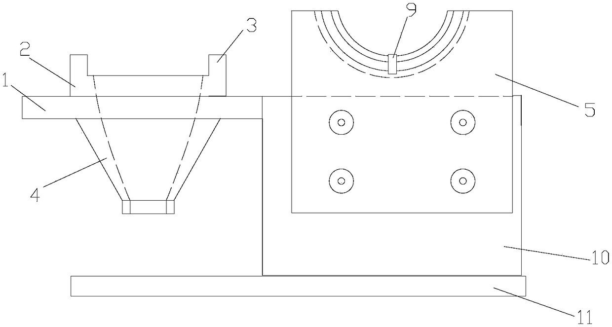
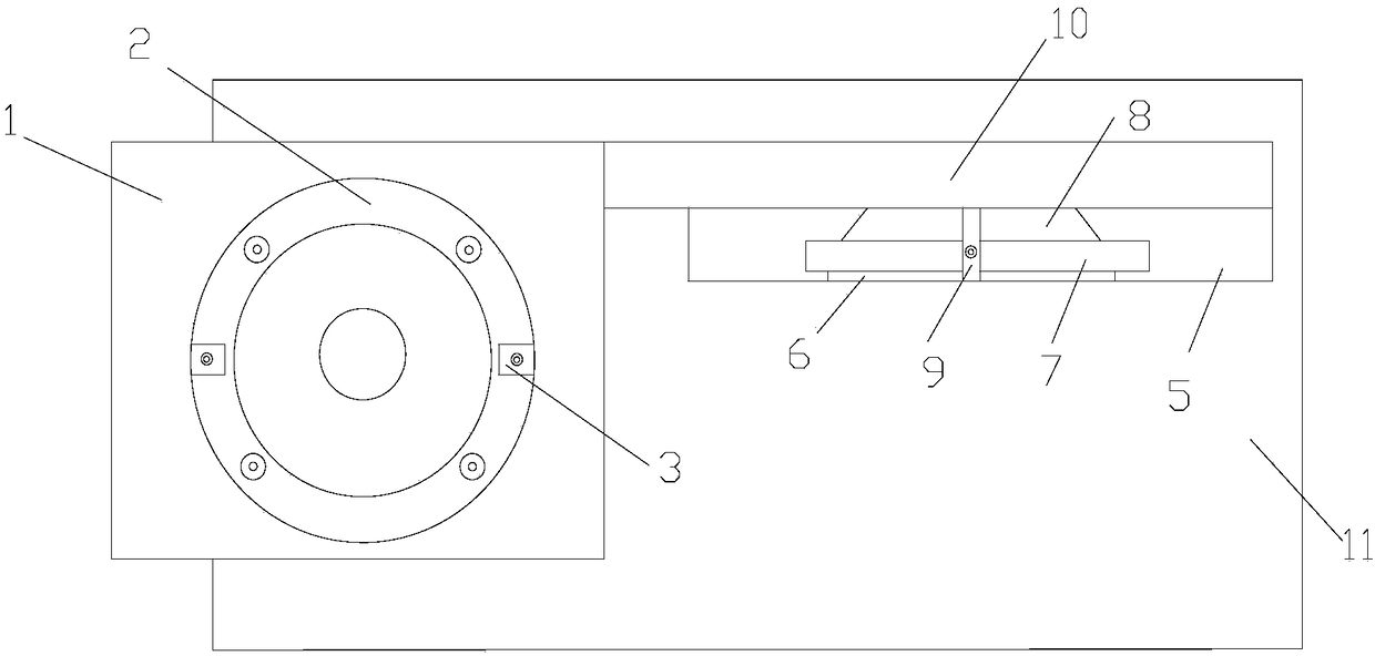
[0018] Such as figure 1 , 2 As shown, a clamping device for a numerically controlled tool chuck includes a bracket, a vertically placed clamping mechanism for a numerically controlled tool chuck fixed on the bracket, and a horizontally placed clamping mechanism for a numerically controlled tool chuck;

[0019] The vertical clamping mechanism of the numerical control tool chuck includes a horizontal fixed plate 1 fixedly connected with the support, and a through hole is provided on the horizontal fixed plate 1, and a positioning ring 2 is fixed on the top surface of the horizontal fixed plate 1 by screws, and the horizontal fixed plate The bottom surface of the plate 1 is fixed with a clamping sleeve 4, the inner cavity of the cl...


PUM


Abstract

The invention discloses a clamping device of a numerical control tool chuck. The clamping device comprises a numerical control tool chuck vertical placing and clamping mechanism and a numerical control tool chuck horizontal placing and clamping mechanism; the numerical control tool chuck is inserted into a cavity formed by a positioning ring, a through hole and a clamping sleeve after being disassembled; the lower end of the numerical control tool chuck is also conical, so that the numerical control tool chuck can be well matched with the vertical placing and clamping mechanism for clamping, and an annular protrusion on the numerical control tool chuck abuts against the top surface of the positioning ring; the numerical control tool chuck can also be placed on the horizontal placing and clamping mechanism after being disassembled; and the cone at the lower end of the numerical control tool chuck is clamped in a third positioning groove, the annular protrusion on the numerical control tool chuck is correspondingly clamped in a second positioning groove, the part at the upper end of the numerical control tool chuck is clamped in a first positioning groove, and the outer peripheral surfaces of the three parts of the numerical control tool chuck are correspondingly in tangency with the bottom surface of the first positioning groove and the bottom surface of the second positioning groove. According to the clamping device, the clamping effect is good, the numerical control tool chuck does not shake, and the stability is good.

Description

technical field [0001] The invention relates to a clamping device for a numerically controlled tool holder. Background technique [0002] The CNC tool chuck needs to be disassembled and installed frequently to facilitate tool replacement. The disassembled CNC tool chuck needs to be placed with a proprietary clamping device, because the CNC tool chuck is a precision device. If it is damaged or collided with deformation, it will affect the tool. The clamping and machining accuracy of the workpiece. However, the prior art lacks the exclusive clamping device of the CNC tool holder. Contents of the invention [0003] The purpose of the present invention is to provide a clamping device for CNC tool holders, which solves the technical problem of the lack of proprietary clamping devices for CNC tool holders in the prior art, resulting in easy damage or collision deformation of the disassembled CNC tool holders . [0004] In order to achieve the above object, the patent technica...

Claims


Application Information

Patent Timeline
Patent Type & Authority Applications(China)
IPC IPC(8): B23Q3/00
CPCB23Q3/00
Inventor 郑三豹
Owner 南京雄豹精密机械有限公司
Why Eureka
Try Eureka