Laminated water-cooling radiator

A water-cooled radiator and layered technology, which is applied in the types of heat exchangers, indirect heat exchangers, laminated components, etc., can solve the problems of cumbersome manufacturing process, and achieve the advantages of simple manufacturing process, large contact area and good water cooling effect. Effect

Pending Publication Date: 2019-02-26
东莞运宏模具有限公司
View PDF0 Cites 6 Cited by
  • Summary
  • Abstract
  • Description
  • Claims
  • Application Information

AI Technical Summary

Problems solved by technology

[0002] The radiator is a device used to cool the object to be cooled. Most of the existing radiators use fins, but they have the disadvantage of cumbersome manufacturing process.

Method used


Image

  • Laminated water-cooling radiator
  • Laminated water-cooling radiator
  • Laminated water-cooling radiator

Examples


Embodiment 1

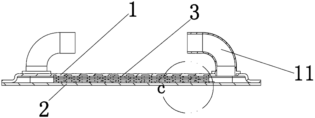
[0037] Embodiment 1 of the present invention provides a laminated water-cooled radiator, such as Figure 1-5 As shown, it includes a cover plate 1, a bottom plate 2, and a laminated water-cooled plate 3;

[0038] The cover plate 1 is arranged on the top of the laminated water-cooled plate 3 stacked symmetrically and has at least one water inlet 11;

[0039] The bottom plate 2 is arranged at the bottom of the laminated water-cooled plate 3 that is stacked in multiple layers symmetrically and is provided with a water outlet 21;

[0040] The laminated water-cooling plate 3 is symmetrically stacked in multiple layers and located between the cover plate 1 and the bottom plate 2, and the openings on the symmetrically stacked laminated water-cooling plate 3 form a water flow channel.

[0041] Specifically, at least two laminated water cooling plates 3 are stacked.

[0042] The laminated water cooling plate 3 of each layer is a rectangular plate, and the openings on the laminated wa...

Embodiment 2

[0048] Embodiment 2 of the present invention provides a laminated water-cooled radiator, such as Figure 6-12 As shown, it includes a cover plate 1, a bottom plate 2, and a laminated water-cooled plate 3;

[0049] The cover plate 1 is arranged on the top of the laminated water-cooled plate 3 stacked symmetrically and has at least one water inlet 11;

[0050] The bottom plate 2 is arranged at the bottom of the laminated water-cooled plate 3 that is stacked in multiple layers symmetrically and is provided with a water outlet 21;

[0051] The laminated water-cooling plate 3 is symmetrically stacked in multiple layers and located between the cover plate 1 and the bottom plate 2, and the openings on the symmetrically stacked laminated water-cooling plate 3 form a water flow channel.

[0052] Specifically, at least two laminated water cooling plates 3 are stacked.

[0053] The laminated water-cooling plate 3 of each layer is a circular plate, and the center of each layer of the la...


PUM


Abstract

The invention discloses a laminated water-cooling radiator, which comprises a cover plate, a bottom plate and a laminated water-cooling plate. The cover plate is arranged on the top of the laminated water-cooling plate which is symmetrically stacked with a plurality of layers and is provided with at least one water inlet; the bottom plate is arranged at the bottom of the laminated water cooling plate and is provided with a water outlet; the laminated water cooling plate is symmetrically stacked with a plurality of layers and is arranged between the cover plate and the bottom plate, and holes in the laminated water cooling plate are combined to form a water flow channel. According to the invention, hot water is introduced into the laminated water cooling plates through the water inlet of the cover plate, the hot water flows from top to bottom through the water flow channel of the laminated water cooling plate, and the heat is brought out and is finally discharged through the water outlet at the bottom plate to achieve the temperature ramping and water cooling effects; the structure is simple, the manufacturing process is simple, the contact area is large, and a better water coolingeffect can be achieved.

Description

technical field [0001] The invention belongs to the technical field of radiators, and in particular relates to a laminated water-cooled radiator. Background technique [0002] A radiator is a device used to cool an object to be cooled. Most of the existing radiators use fins, but they have the disadvantage of cumbersome manufacturing process. Contents of the invention [0003] In view of this, the main purpose of the present invention is to provide a laminated water cooling radiator. [0004] In order to achieve the above object, technical solution of the present invention is achieved in that way: [0005] An embodiment of the present invention provides a laminated water-cooled radiator, including a cover plate, a bottom plate, and a laminated water-cooled plate; [0006] The cover plate is arranged on the top of the symmetrically stacked multi-layer laminated water-cooled plate and is provided with at least one water inlet; [0007] The bottom plate is arranged at the ...

Claims


Application Information

Patent Timeline
IPC IPC(8): F28D1/03F28F3/08
CPCF28D1/0308F28F3/08
Inventor 陈科吉杨波
Owner 东莞运宏模具有限公司
Why Eureka
Try Eureka