Spinning bracket convenient to move

A one-sided, movable rod technology, applied in the direction of machine/stand, supporting machine, mechanical equipment, etc., can solve the problems of inconvenience, inseparability, fixed height, etc., and achieve the effect of avoiding self-falling

Inactive Publication Date: 2019-02-26
WENZHOU POLYTECHNIC
View PDF9 Cites 0 Cited by
  • Summary
  • Abstract
  • Description
  • Claims
  • Application Information

AI Technical Summary

Problems solved by technology

[0002] With the rapid rise of my country's industry, the textile industry has also developed rapidly. The original meaning of textile is taken from the general term of spinning and weaving. However, with the continuous development and improvement of the textile knowledge system and discipline system, especially non-woven textile materials and After the emergence of technologies such as three-dimensional composite weaving, the current textile is not only traditional hand spinning and weaving, but also non-woven technology, modern three-dimensional weaving technology, modern electrostatic nano-netting technology, etc., and textile machines cannot do without Textile support, but the height of the existing textile support is fixed, which brings inconvenience to people's use

Method used


Image

  • Spinning bracket convenient to move
  • Spinning bracket convenient to move
  • Spinning bracket convenient to move

Examples


Embodiment Construction

[0021] The present invention will be described in further detail below in conjunction with the embodiments given in the accompanying drawings.

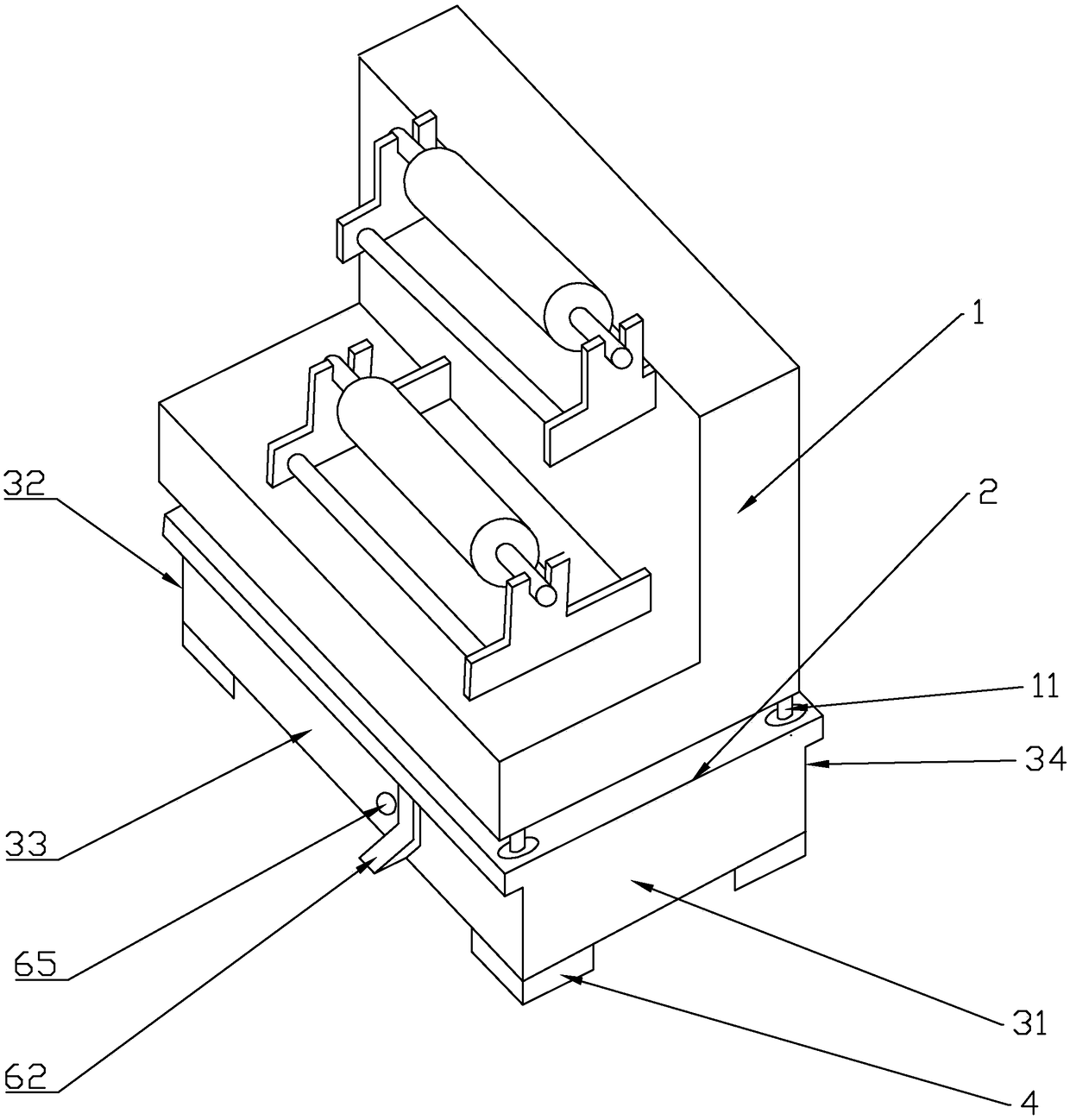
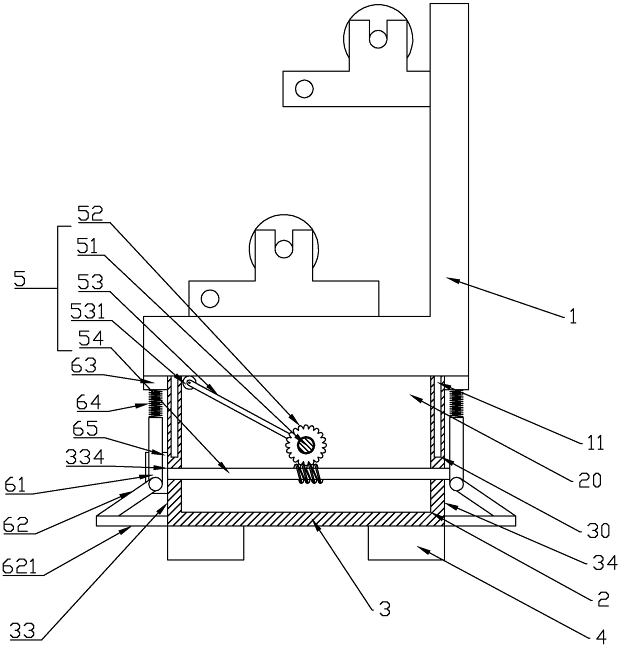
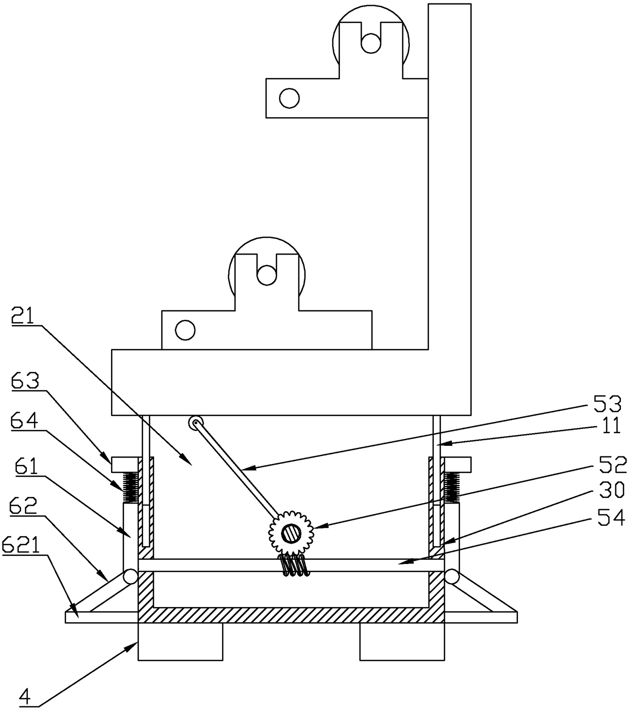
[0022] refer to Figure 1 to Figure 8 As shown, a spinning frame that is easy to move in this embodiment includes a frame body 1 and a control box 2 located below the frame body 1. The control box 2 is provided with an accommodation cavity 20, and the control box 2 includes a Bottom plate 3, the side of the bottom plate 3 facing away from the bracket body 1 is also provided with a support 4, the control box 2 includes a first side plate 31 and a second side plate 32 on both sides of the bottom plate 3 in the width direction, the first side plate 32 One side plate 31 and the second side plate 32 are provided with a limiting groove 30 on one side facing the bracket body 1, and the bracket body 1 is provided with a limiting column 11, and the limiting column 11 is located in the limiting groove 30. The limit groove 30 is used to limit t...


PUM


Abstract

The invention discloses a spinning bracket convenient to move, which comprises a bracket body and a control box, wherein an accommodating cavity is formed in the control box; the control box comprisesa bottom plate; a support is further arranged on the bottom plate; the control box comprises a first side plate and a second side plate which are arranged at two sides of the bottom plate in the width direction; limiting grooves are formed on the surfaces of the first side plate and the second side plate, facing the bracket body; a limiting column is arranged on the bracket body; a lifting mechanism is arranged in the accommodating cavity; the lifting mechanism comprises a rotating rod which is rotatably arranged between the first side plate and the second side plate; a turbine sleeves the rotating rod; the turbine is provided with an abutting rod; the control box is provided with an opening; one end of the abutting rod is fixed on the turbine, and the other end of the abutting rod extends out of the opening and abuts against the bracket body; the lifting mechanism further comprises a worm engaged with the turbine; the control box comprises a third side plate and a fourth side plate on two sides of the bottom plate in the length direction; the third side plate and the fourth side plate are provided with openings through which two ends of the worm pass, and the control box is further provided with a driving mechanism.

Description

technical field [0001] The invention relates to a textile support, in particular to an easy-to-move spinning support. Background technique [0002] With the rapid rise of my country's industry, the textile industry has also developed rapidly. The original meaning of textile is taken from the general term of spinning and weaving. However, with the continuous development and improvement of the textile knowledge system and discipline system, especially non-woven textile materials and After the emergence of technologies such as three-dimensional composite weaving, the current textile is not only traditional hand spinning and weaving, but also non-woven technology, modern three-dimensional weaving technology, modern electrostatic nano-netting technology, etc., and textile machines cannot do without Textile support, but its height is fixed in existing textile support, brings inconvenience for people's use. Contents of the invention [0003] Aiming at the deficiencies in the prior...

Claims


Application Information

Patent Timeline
Patent Type & Authority Applications(China)
IPC IPC(8): F16M11/26
CPCF16M11/26
Inventor 张衡孙天赦
Owner WENZHOU POLYTECHNIC
Why Eureka
Try Eureka