
Tube feeding device

A feeding device and feeding technology, applied in the field of pipe feeding devices, can solve problems such as excessive speed, no reciprocation of feeding, processing waste and increased production costs, etc., and achieve the effects of reasonable structural design, guaranteed use effect, and good coordination.

Inactive Publication Date: 2019-02-26
陈振清
View PDF0 Cites 0 Cited by
  • Summary
  • Abstract
  • Description
  • Claims
  • Application Information

AI Technical Summary

Problems solved by technology

[0003] The structural design of the existing pipe feeding device is unreasonable; there are problems of no reciprocation or too fast feeding; resulting in waste of processing and increased production costs

Method used


Image

  • Tube feeding device
  • Tube feeding device

Examples


Embodiment Construction

[0019] The present invention will be further explained below in conjunction with the accompanying drawings and embodiments.

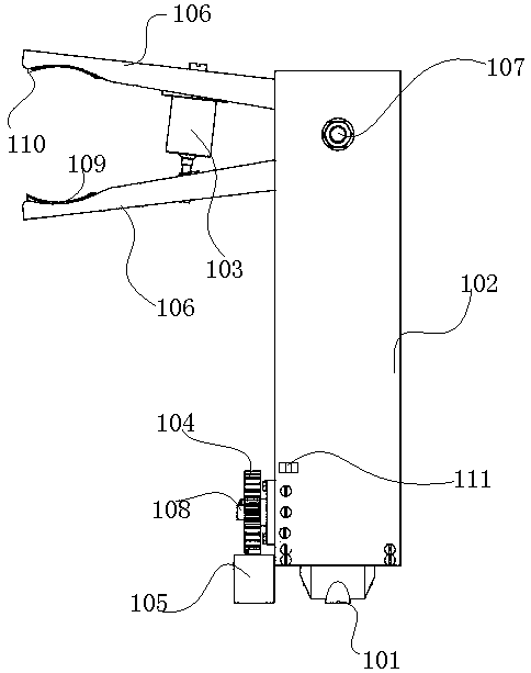
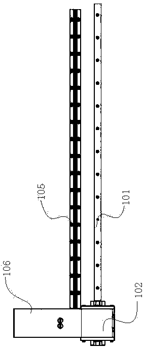
[0020] Such as Figure 1-2 As shown, a pipe material feeding device, the feeding device includes a feeding guide rail 101, a feeding support 102 arranged on the feeding guide rail 101, a clamping claw arranged on the feeding support 102, and a short stroke between the clamping claws Hydraulic cylinder 103, the sliding gear 104 that is located on the feed support 102, the rack 105 that is compatible with the slide gear 104 and the motor that is compatible with the slide gear 104; The feed guide rail 101 is an arc feed guide rail; The feed support 102 is provided with the give way groove that is adapted with arc-shaped feeding guide rail 101; Clamping claw comprises symmetrically set clamping minions 106, and clamping claw is hinged on the feed bearing 102 by positioning pin 107, and sliding gear 104 is on rack 105 Do reciprocating motion on the top, and...


PUM


Abstract

The invention discloses a tube feeding device. The feeding device comprises a feeding guiderail, a feeding support arranged on the feeding guiderail, gripper jaws arranged on the feeding support, a short stroke hydraulic cylinder arranged between the gripper jaws, a sliding gear arranged on the feeding support, a rack adapted to the sliding gear, and a motor adapted to the sliding gear; the feeding guiderail is an arc feeding guiderail; the feeding support is provided with a relief groove adapted to the arc feeding guiderail; each gripper jaw comprises symmetrically-arranged clamping claws, the gripper jaws are hinged to the feeding support through locating pins, and the sliding gear does reciprocating motion on the rack and drives the feeding support to do reciprocating motion on the feeding guiderail. The tube feeding device is capable of stably feeding a tube to a preset position point of a next procedure, and can meet the requirements of the overall design and satisfy the use requirements.

Description

technical field [0001] The invention relates to the field of machinery, in particular to a pipe feeding device. Background technique [0002] When processing pipes and fittings, it needs to be cut to length, but because pipes are generally welded by steel plates or steel strips, clamping deformation or plastic deformation will occur when cutting to length; therefore, the feeding device when cutting to length and clamping devices are particularly important. [0003] The structural design of the existing pipe material feeding device is unreasonable; there is a problem of no reciprocation or too fast feeding; resulting in waste of processing and increased production costs. Contents of the invention [0004] The purpose of the present invention is to overcome the problems of the prior art and provide a pipe feeding device. [0005] A pipe material feeding device of the present invention, the feeding device includes a feeding guide rail, a feeding support provided on the feed...

Claims


Application Information

Patent Timeline
IPC IPC(8): B23D33/02B23D33/10
CPCB23D33/02B23D33/006B23D33/10
Inventor 陈振清
Owner 陈振清
Learn More