Magnetic sheet type transformer with low mounting height

A technology of installation height and transformer, applied in the field of transformers, can solve the problems affecting the current passing ability and reliability of the winding, the power density of the planar transformer cannot be maximized, and the resistance value of the electrical connection point is increased.

Pending Publication Date: 2019-02-22
DONGGUAN DAZHONG ELECTRONICS
View PDF0 Cites 0 Cited by
  • Summary
  • Abstract
  • Description
  • Claims
  • Application Information

AI Technical Summary

Problems solved by technology

Due to the complicated structural design of the current planar transformer, it is generally combined with a PCB board or a coil, and is assembled by open and manual stacking. The electrical connection points of the winding are connected externally, and the traditional heating welding (silver or tin) process is adopted. Therefore, The planar transformer needs to reserve a large welding space in the structure and process design, so the power density of the planar transformer cannot be maximized
Secondly, due to the traditional welding process, a large number of skilled assembly workers are required to assemble the components, which will affect the production cost and reliability of the transformer
Furthermore, because the traditional welding process is affected by factors such as welding temperature, time control differences, welding materials, and welding modes, it may cause the resistance value of each electrical connection point to increase and become unstable, thereby affecting the current passing capacity of each winding and Reliability, which in turn affects the quality of planar transformers

Method used


Image

  • Magnetic sheet type transformer with low mounting height
  • Magnetic sheet type transformer with low mounting height
  • Magnetic sheet type transformer with low mounting height

Examples


Embodiment Construction

[0024] The present invention is further described in conjunction with the following examples.

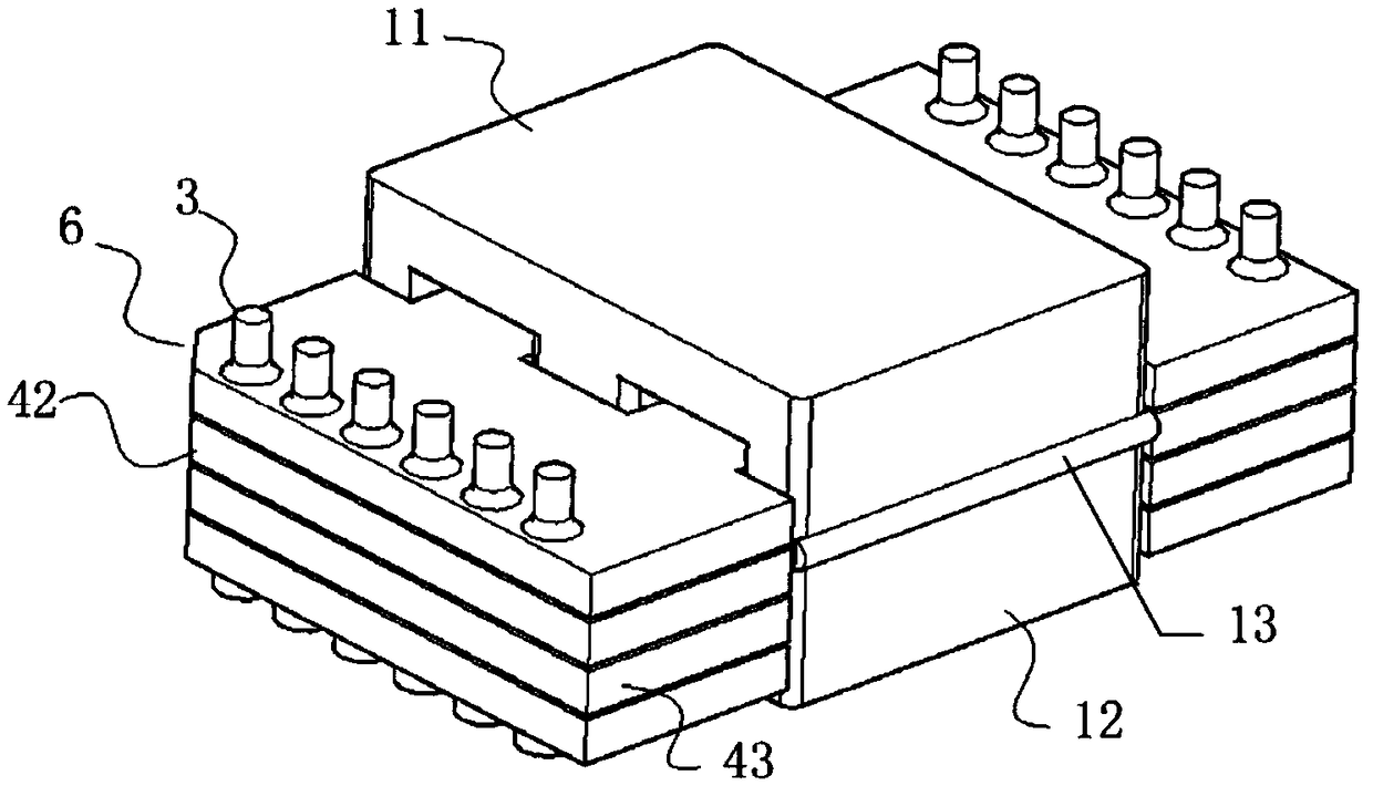
[0025] Depend on Figure 1 to Figure 6 It can be seen that a low installation height magnetic chip transformer described in this embodiment includes upper and lower symmetrical upper E-shaped magnetic cores 11 and lower E-shaped magnetic cores 12; the upper E-shaped magnetic core 11 and the lower E-shaped magnetic core There are multi-layer PCB copper clad laminates between the cores 12;

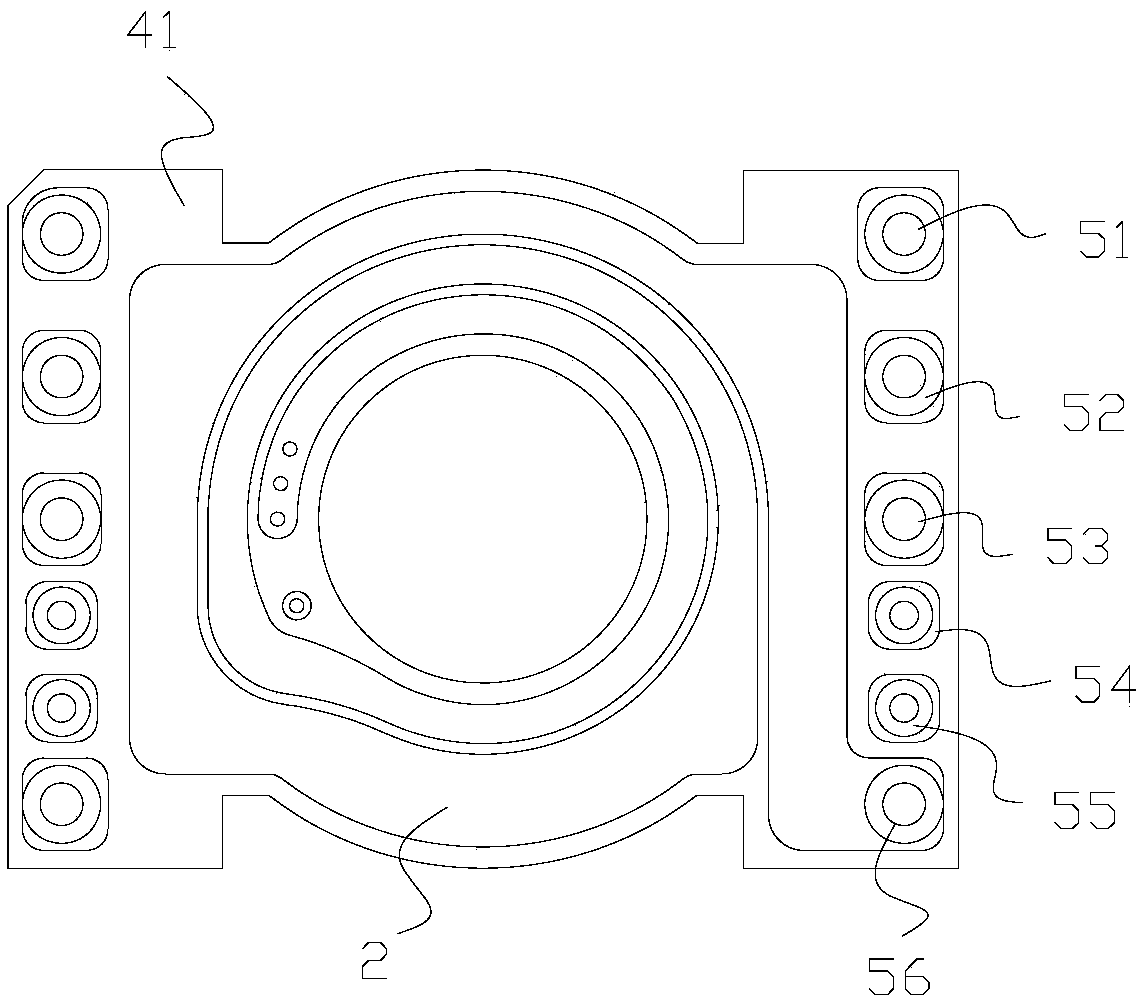
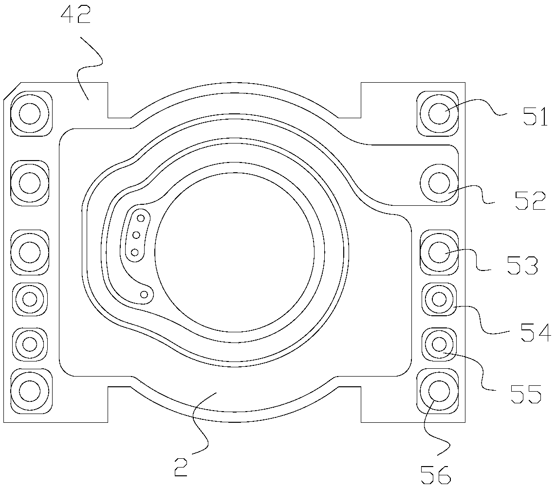
[0026] Each of the PCB copper clad boards includes a PCB board and a winding 2 etched on the PCB board; each PCB board and each winding 2 are provided with through holes;

[0027] The low installation height magnetic chip transformer includes a conductive column 3 for conducting conduction between each PCB board and each winding 2; .

[0028] Specifically, the low-installation-height magnetic chip transformer described in this embodiment adopts a plane in which 2 turns of corresponding windings...


PUM


Abstract

The invention relates to the technical field of transformers, in particular to a magnetic sheet type transformer with the low mounting height. The magnetic sheet type transformer is characterized by comprising an upper E-shaped magnetic core and a lower E-shaped magnetic core which are symmetric up and down; multiple layers of PCB copper-clad boards are arranged between the upper E-shaped magneticcore and the lower E-shaped magnetic core; each PCB copper-clad board comprises a PCB and a winding etched in the PCB; each PCB and each winding are both provided with a through hole; the magnetic sheet type transformer with the low mounting height comprises conducting posts; the conducting posts penetrate into the through holes of the PCBs and the through holes of the windings. The windings withthe corresponding number of turns are etched in the PCBs, and the plane transformer achieves the effects that highly-integrated modularization is achieved, the power density is highest, and the manufacturing process is standardized. In addition, the conducting posts penetrate into electrical connecting point parts, so that conduction is achieved, a traditional welding process is replaced, and theproduction efficiency is improved.

Description

technical field [0001] The invention relates to the technical field of transformers, in particular to a low installation height magnetic chip transformer. Background technique [0002] Most of the existing magnetic chip planar transformers (especially for high current and high power applications) use copper skin as the primary / secondary winding, stack multiple such windings together, and then form a transformer together with the magnetic core. Due to the complicated structural design of the current planar transformer, it is generally combined with a PCB board or a coil, and is assembled by open and manual stacking. The electrical connection points of the winding are connected externally, and the traditional heating welding (silver or tin) process is adopted. Therefore, The planar transformer needs to reserve a large welding space in the structure and process design, so the power density of the planar transformer cannot be maximized. Secondly, due to the traditional welding ...

Claims


Application Information

Patent Timeline
IPC IPC(8): H01F27/28H01F27/24
CPCH01F27/24H01F27/28H01F27/2804H01F2027/2809H01F2027/2819
Inventor 杨声斌李正中李经伟
Owner DONGGUAN DAZHONG ELECTRONICS
Why Eureka
Try Eureka