
Method for generating three-dimensional multi-focal spot array based on spatial dipole array

A method for generating dipoles, applied in optical components, optics, instruments, etc., which can solve the lengthy iterative optimization process, the uniformity of 3D focal spots, the difficulty in controlling the number, position and spacing, the lack of simplicity and flexibility, etc. Questions to achieve a controllable number, customizable location and spacing, and the same intensity

Active Publication Date: 2019-02-22
QUANZHOU NORMAL UNIV
View PDF7 Cites 4 Cited by
  • Summary
  • Abstract
  • Description
  • Claims
  • Application Information

AI Technical Summary

Problems solved by technology

[0005] However, the above-mentioned methods for realizing 3D multi-focal spot arrays all have a limitation, that is, a lengthy iterative optimization process is required
Therefore, it lacks simplicity and flexibility, and the uniformity, number, position and spacing of the generated three-dimensional focal spots are not easy to control

Method used


Image

  • Method for generating three-dimensional multi-focal spot array based on spatial dipole array
  • Method for generating three-dimensional multi-focal spot array based on spatial dipole array
  • Method for generating three-dimensional multi-focal spot array based on spatial dipole array

Examples


Embodiment 1

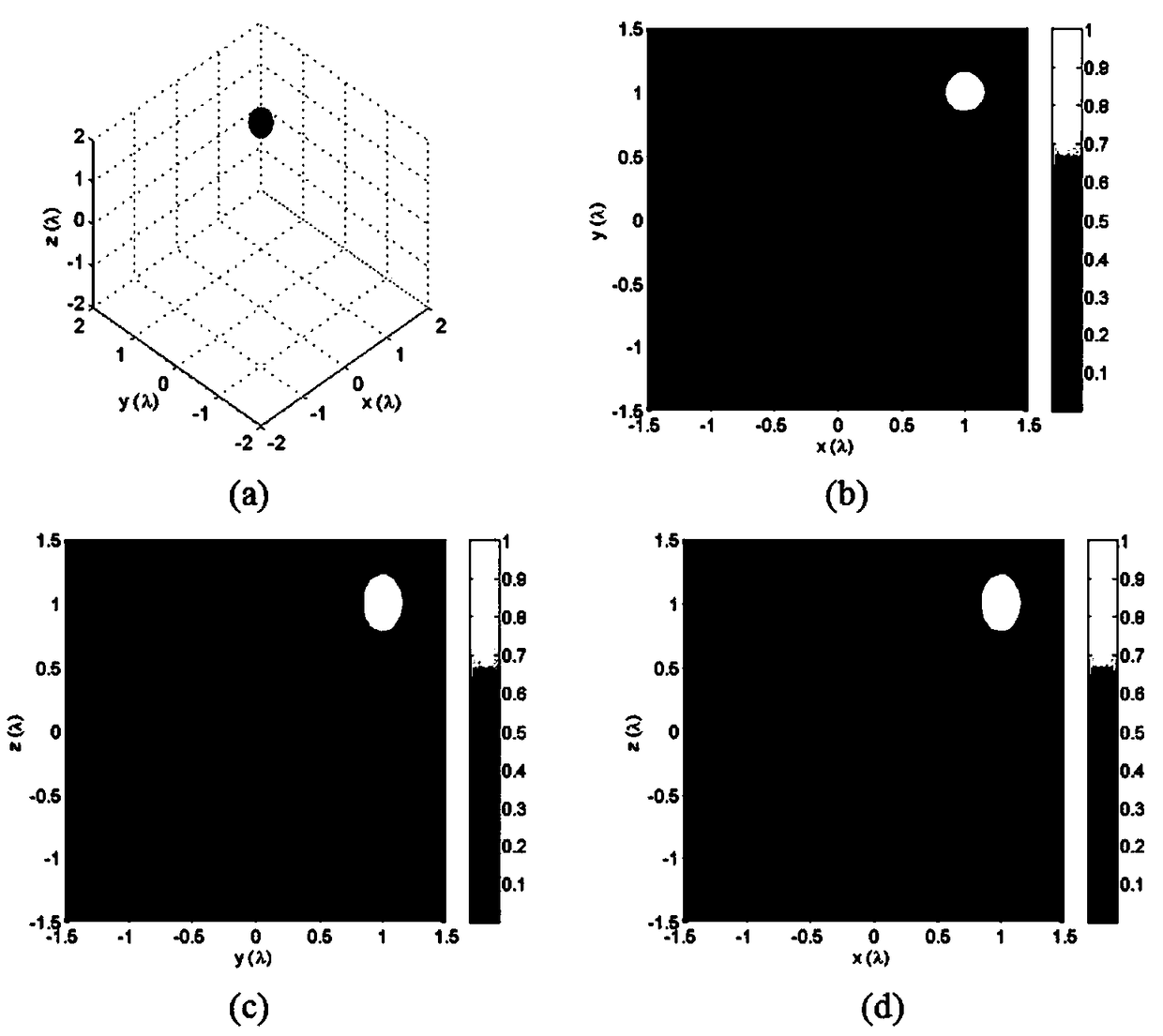
[0089] The constant C is normalized to 1 because it has nothing to do with the shape of the focal spot. At present, reflective lenses or hyperplane lenses are used, and the maximum convergence angle can reach θ max = π / 2. As a first example, suppose a virtual dipole is placed near the focal point of the focusing system (1λ, 1λ, 1λ), and its radiation field is completely collected by the 4π focusing system and reversely converged to the focal region. Using formulas (9)-(11) and (14), the three-dimensional single focal spot located near the focal region can be easily obtained, such as figure 2 (a) shown. from figure 2 It can be clearly seen in (a) that the three-dimensional iso-intensity surface distribution of the focal spot (I=0.5Imax) appears as an ellipsoid rotating around the Z axis, and the reason is that the polarization direction of the virtual dipole is along the Z axis direction. The projections of the focal spot on the XY plane, YZ plane and XZ plane are concentr...

Embodiment 2

[0091] The method of this embodiment can also generate multiple focal spots located at any position in the focal region. image 3 The iso-intensity surface distribution of multiple focal spots at predetermined locations is given. It can be seen that the position of each focal spot is controllable, and the intensity and shape are the same. Similarly, the center position of the l-th focal spot only depends on and is equal to the position coordinates of the l-th virtual dipole in the focal area (x l ,y l ,z l ). image 3 Among them, (a) is two focal spots located at (-λ,λ,λ) and (λ,-λ,-λ); (b) is located at (-λ,-λ,-λ), (0,0 ,0), and three focal spots of (λ,λ,λ); (c) is located at (λ,λ,-λ), (-λ,λ,λ), (-λ,-λ,λ) , and four focal spots of (λ,-λ,λ).

Embodiment 3

[0093] Arrange multiple virtual dipoles along a straight line to form a dipole linear array, and apply formulas (6)-(8), (10), (11) and (14), and a multi-focal Spotted linear array. Figure 4 (a), (b) and (c) respectively give three linear arrays of focal spots arranged along the X-axis, Y-axis and Z-axis. Figure 4 Among them, (a) is that the three focal spots are respectively located at x 1 = -λ,x 2 =0,x 3 =λ; (b) three focal spots are located at y 1 = -λ,y 2 =0,y 3 =λ; (c) is the three focal spots located at z 1 = -λ,z 2 = 0, z 3 =λ.


PUM


Abstract

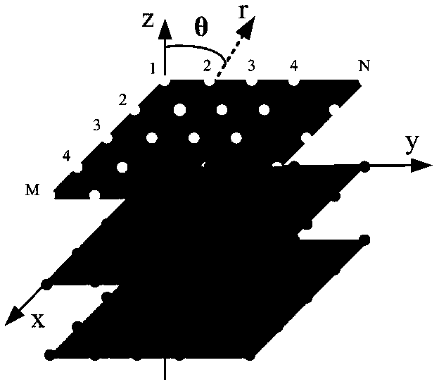
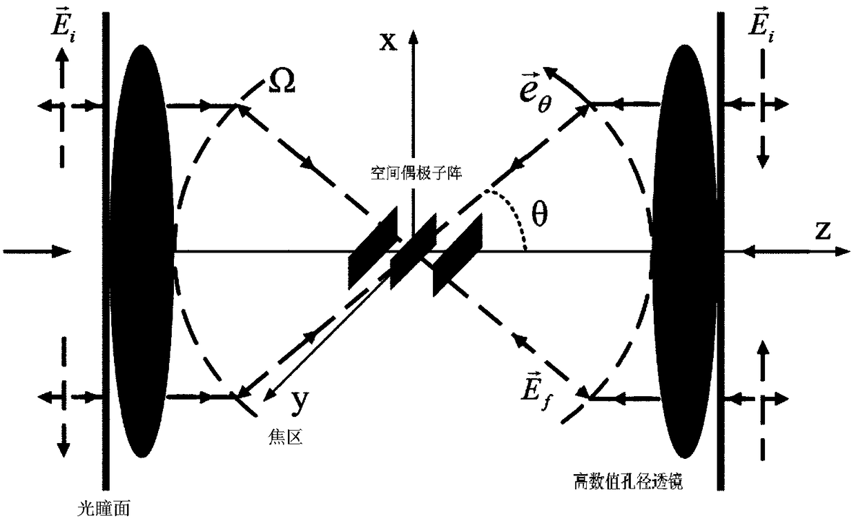
The invention relates to a method for generating a three-dimensional multi-focal spot array based on a spatial dipole array. Two high-numerical-aperture (NA) lenses are used for form a 4pai focusing system; a virtual spatial dipole array is arranged at a focal region of the4pai focusing system; the two high-NA lenses collect the all radiation field of the spatial dipole array completely from imagespace and then the radiation field is collimated to a pupil plane, and an inverse problem is solved to obtain electric field distribution on the pupil plane; and then field distribution on the pupilplane is regarded as an incident field and is transmitted to the focal region in a reverse direction and a three-dimensional multi-focal spot array with the predetermined characteristic is generated near the focal regions of the high-NA lenses. According to the invention, no tedious iterative optimization process is needed during generation of the three-dimensional multi-focal spot array by usingthe radiation field of the spatial dipole array; and each focal spot has the same appearance and intensity, the number of the focal spots is controllable and the positions and space of the focal spotsare customized.

Description

technical field [0001] The invention relates to the technical field of generating a three-dimensional multi-focal spot array, in particular to a method for generating a three-dimensional multi-focal spot array based on a space dipole array. Background technique [0002] The subwavelength focal spots formed under the tight focusing of high numerical aperture (NA) lenses have important applications in microscopy, optical data storage, laser micro-nano processing, and high-resolution optical imaging. Therefore, many methods for generating focal spots have been reported numerically and experimentally. [0003] For example, in the earlier period, scholars focused on generating one focal spot or multiple focal spots along the optical axis near the focal region, that is, a one-dimensional spot array. However, in some specific applications, such as parallel imaging and multi-point processing, two-dimensional focal spot arrays are required due to their inherent properties of high ef...

Claims


Application Information

Patent Timeline
Patent Type & Authority Applications(China)
IPC IPC(8): G02B27/00
CPCG02B27/00G02B27/0012
Inventor 余燕忠林雪华
Owner QUANZHOU NORMAL UNIV
Learn More