
Laser strengthening device for antifriction bearing ring

A technology of laser strengthening and rolling bearings, applied in furnaces, heat treatment equipment, heat treatment furnaces, etc., can solve problems such as stress relaxation, processing deformation, geometric deformation of bearing rings, etc., and achieve the effects of slowing down the relaxation rate, suppressing deformation, and improving stability

Pending Publication Date: 2019-02-22
UNIV OF JINAN
View PDF2 Cites 5 Cited by
  • Summary
  • Abstract
  • Description
  • Claims
  • Application Information

AI Technical Summary

Problems solved by technology

[0007] However, the current laser shock strengthening technology for rolling bearing rings has the following two problems: ① The residual stress generated by laser shock on the surface of the raceway will destroy the mechanical balance of the material inside the ring, thereby causing geometric deformation of the bearing ring; Under the action of contact alternating load, the favorable residual compressive stress generated by laser shock on the surface of the ring raceway is not stable, and stress relaxation is easy to occur
During the laser strengthening process of the bearing ring, the fixture lacks constraints on the deformation of the bearing ring, which is prone to processing deformation

Method used


Image

  • Laser strengthening device for antifriction bearing ring
  • Laser strengthening device for antifriction bearing ring
  • Laser strengthening device for antifriction bearing ring

Examples


Embodiment Construction

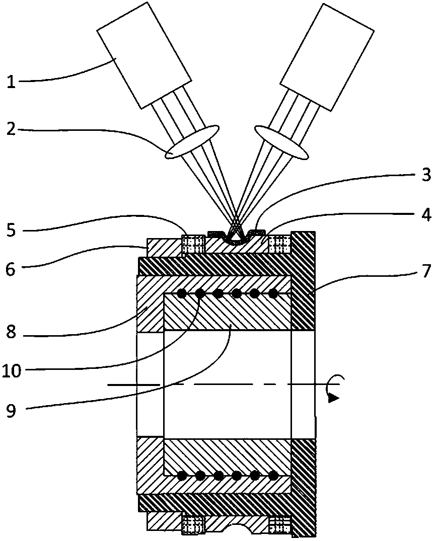
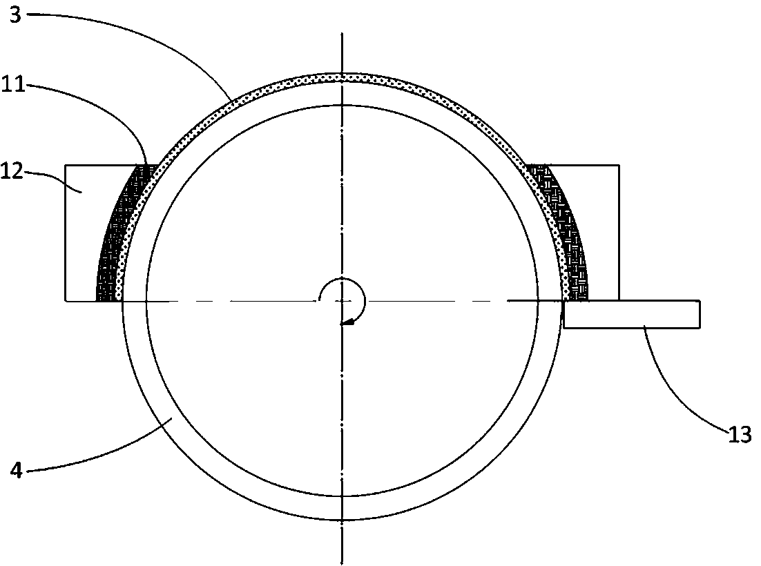
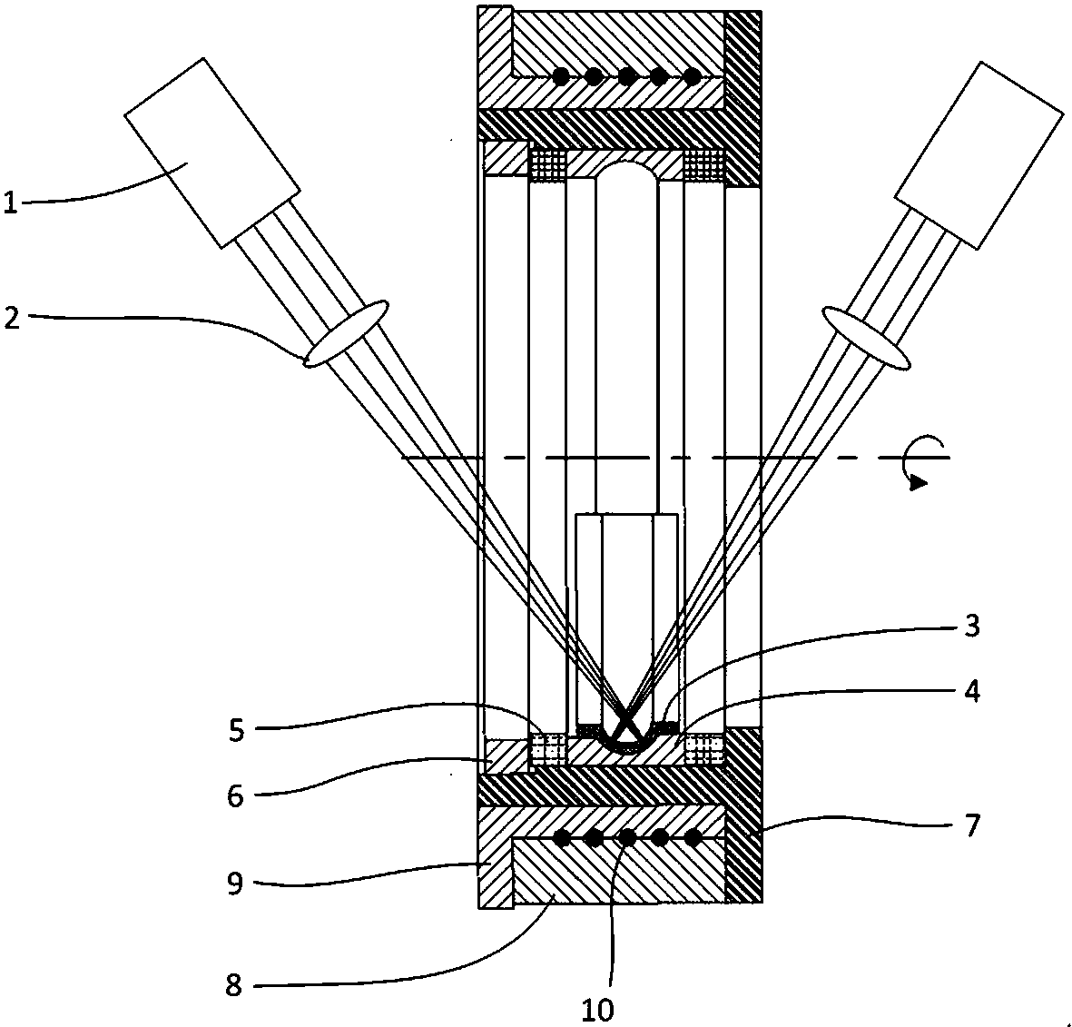
[0046] It can be understood that due to the limitation of the spot A of the laser emitted by the laser, it is impossible to strengthen the raceway of the bearing ring 4 at the same time, which will cause unbalanced stress distribution, that is, processing stress will be generated, and Therefore, the deformation of the bearing ring 4 will occur. Although the deformation is not large, for high-precision parts such as bearings (generally IT6 or IT7 precision), the laser-enhanced processing deformation is enough to make the geometric shape out of tolerance.

[0047] Regarding laser strengthening, the principle is to first coat a layer of black paint on the surface of the workpiece to form a black paint layer. The black paint layer has a better absorption effect on light, also known as the absorbing layer. When laser spot A falls on the absorbing layer, the part of the black paint covered by spot A is heated and vaporized to form plasma, which produces a burst, causing the surface o...


PUM


Abstract

The invention discloses a laser strengthening device for an antifriction bearing ring. The laser strengthening device for the antifriction bearing ring comprises a positioning sleeve, a heating assembly, axial constraints, a drive device, a laser and a constraining plate, wherein first axle hole fit is formed between one of two column faces of the positioning sleeve and the assembling face of thebearing ring; the heating assembly is arranged on the other column face of the positioning sleeve; the axial constraints include the first end constraint and the second end constraint, the two ends ofthe bearing ring are positioned and locked through the two constraints, and at least one of the constraints is detachably connected with the positioning sleeve; the drive device is used for driving the positioning sleeve to rotate around own axis; laser light of the laser is projected to a roller path; and the constraining plate is a sleeve-shaped plate cooperating with the roller path face of the bearing ring and is used for mechanically covering the roller path, and the constraining plate is a transparent plate opposite to the laser light projected by the laser. By means of the laser strengthening device, the deformation caused by thermal stress during laser strengthening of the antifriction bearing ring can be effectively restrained.

Description

technical field [0001] The invention relates to a laser strengthening device for strengthening a rolling bearing ring. Background technique [0002] Rolling bearings are the key basic components of mechanical transmission systems. At present, although my country is a big country in bearing production, it is not a strong country in bearing manufacturing. The manufacturing level of high-performance rolling bearings is far from meeting the needs of high-end equipment development. The development of equipment manufacturing industry. [0003] In addition to the machining accuracy of rolling elements and bearing rings, the factors affecting the service life of rolling bearings are also related to the contact fatigue strength of the raceways on rolling elements and bearing rings. Among them, regarding the improvement of the contact fatigue strength of the upper raceway of the rolling bearing ring, in addition to improving the base material of the bearing steel, the use of surface ...

Claims


Application Information

Patent Timeline
IPC IPC(8): C21D9/40C21D1/09C21D10/00
CPCC21D1/09C21D9/40C21D10/005
Inventor 刘文涛郭宇王守仁杨学峰王砚军吴戍戌王高琦温道胜夏佃秀
Owner UNIV OF JINAN
Learn More