Plastic product residue cutting table

A technology of plastic products and cutting tables, which is applied in metal processing and other directions, can solve the problems of complex structure and inability to collect residual materials, and achieve the effect of easy rotation

Inactive Publication Date: 2019-02-22
佛山迪骏自动化科技有限公司
View PDF1 Cites 2 Cited by
  • Summary
  • Abstract
  • Description
  • Claims
  • Application Information

AI Technical Summary

Problems solved by technology

But the structure of this utility model is comparatively complicated, and the leftover material that is cut can't be collected

Method used


Image

  • Plastic product residue cutting table
  • Plastic product residue cutting table
  • Plastic product residue cutting table

Examples


specific Embodiment approach 1

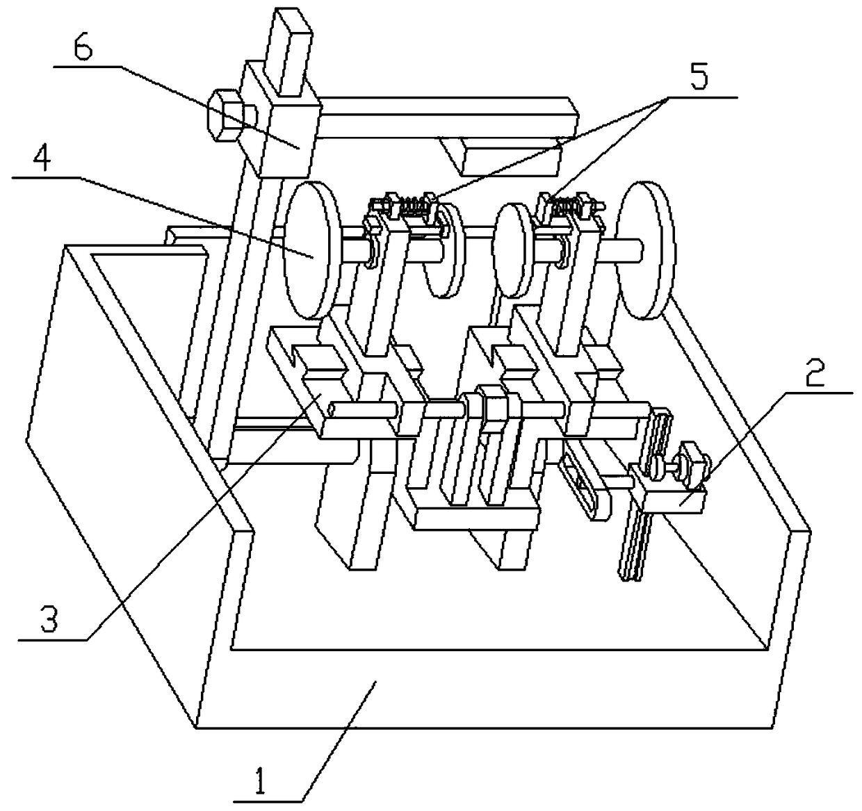
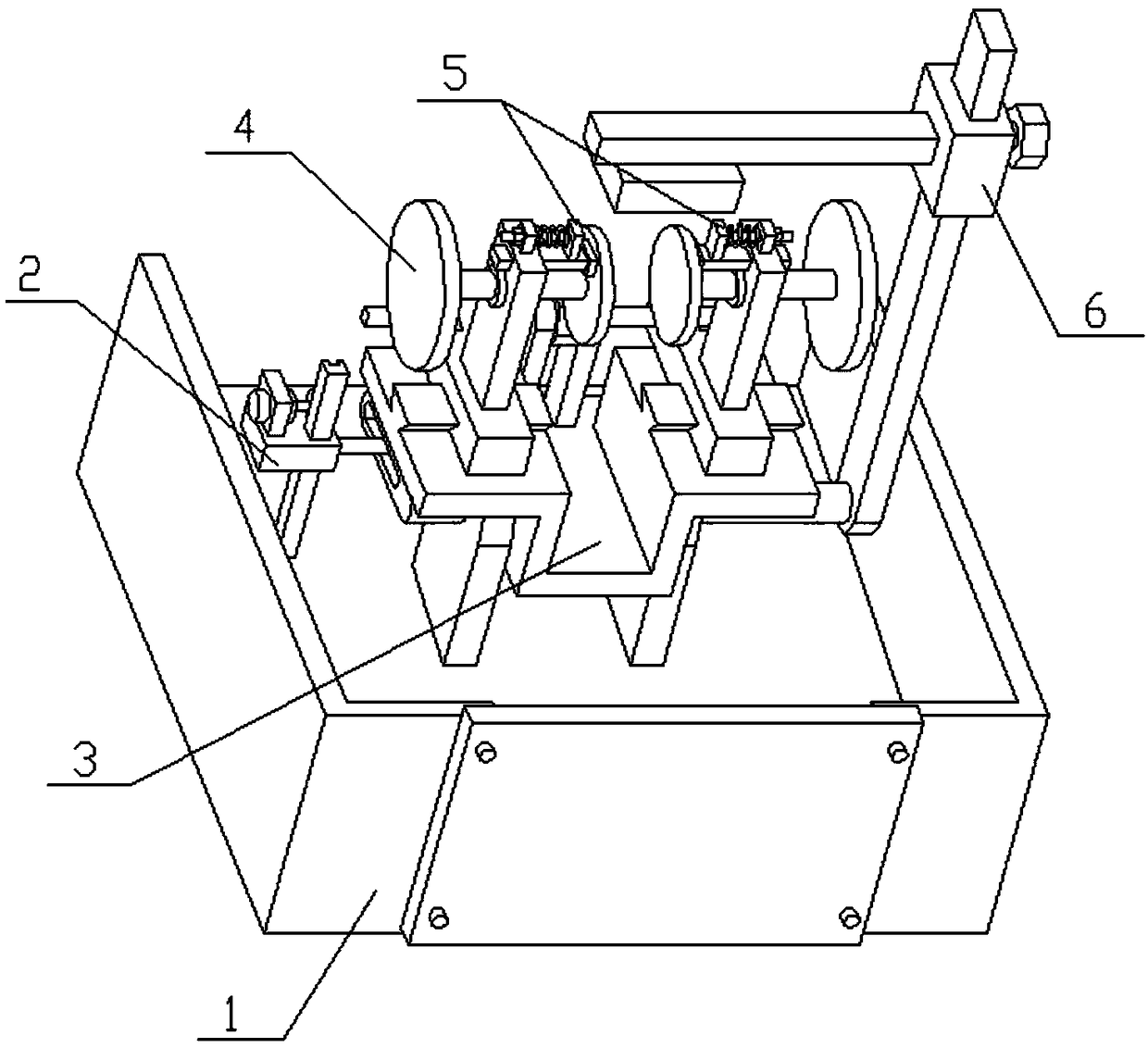
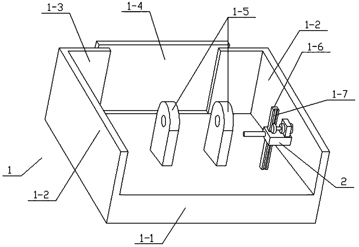
[0026] Combine below Figure 1-10 To illustrate this embodiment, the present invention relates to a cutting device, more specifically a cutting table for leftover plastic products, including a collection box 1, a slider assembly 2, a cutting table 3, a clamping frame 4, and a friction member 5 And the blowing assembly 6, the present invention is used for cutting the flash produced when the plastic blow molding product is made, and the present invention can clamp the plastic blow molding product of different sizes, and the plastic blow molding product after clamping can rotate the axis The axis of 4-5 is a shaft rotation, so as to facilitate the rotation of the plastic blow molding product and facilitate the manual cutting of different positions of the plastic blow molding product; the blowing component 6 can also blow the cut flash into the collection box 1 for collection; The cutting stand 3 can rotate around the axis of the left shaft 3-3, thereby turning the two clamping pi...


PUM


Abstract

The invention relates to a cutting device, in particular to a plastic product residue cutting table. The plastic product residue cutting table is used for cutting flash generated when plastic blow-molded products are manufactured. The plastic blow-molded products with different sizes can be clamped by the plastic product residue cutting table and then rotate with the axis of a rotating shaft as the axis, so that the rotation of the plastic blow-molded products and the manual cutting of different positions of the plastic blow-molded products are facilitated. The cut flash can also be blown intoa collecting box by a blowing assembly and collected. A cutting bench can rotate with the axis of the left shaft as the axis, so that two clamping pieces can be rotated to the front or back positions, and an operator can carry out manual cutting operation at a comfortable position conveniently. A sliding block assembly is rotatably and slidably connected to the collecting box and is slidably connected to the cutting bench. A clamping frame is slidably connected to the cutting bench.

Description

technical field [0001] The invention relates to a cutting device, in particular to a cutting table for waste plastic products. Background technique [0002] The application number is CN201721731727.2, which is a cutting table for waste plastic products. The utility model discloses a cutting table for waste plastic products, which includes a base. The top surface of the base is provided with a mounting groove. The side inner wall is connected with a horizontally arranged first drive motor through bolts, the end of the output shaft of the first drive motor is connected with a cutter, and the two sides of the cutter are provided with baffles that are slidably installed inside the installation groove. The tops of the baffles are all connected with splints, the tops of the sides of the two groups of splints that are close to each other are provided with clamping blocks, and the sides of the two groups of baffles that are far away from each other are connected with first springs. ...

Claims


Application Information

Patent Timeline
IPC IPC(8): B29C37/02B26D7/02B26D7/18
CPCB29C37/02B26D7/02B26D7/1845
Inventor 朱路白杰
Owner 佛山迪骏自动化科技有限公司
Why Eureka
Try Eureka