Convenient-to-remove electrode connection structure for electric heating floor

A technology of electric heating floor and connection structure, applied in the direction of ohmic resistance heating parts, heating elements, etc., can solve the problems of easy desoldering of wires, etc., and achieve the effect of improving convenience and easy rotation

Inactive Publication Date: 2017-12-05
鄢贵龙
View PDF0 Cites 2 Cited by
  • Summary
  • Abstract
  • Description
  • Claims
  • Application Information

AI Technical Summary

Problems solved by technology

[0006] The technical problem to be solved by the present invention is to provide an easily disassembled electrode connection structure of the electric heating floor, which can solve the problem that the electrode connection structure of the existing electric heating floor adopts two magnets whose size is basically the same as the hole. The suction force leads to the problem that the wire is easy to desolder

Method used


Image

  • Convenient-to-remove electrode connection structure for electric heating floor

Examples


Embodiment Construction

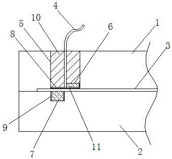
[0017] Such as figure 1 An easily detachable electric heating floor electrode connection structure shown includes a base plate 1, a panel 2, and a conductive heating layer 3 arranged between the base plate 1 and the panel 2. The electrodes 11 of the conductive heating layer 3 are welded with The wire 4 of the conductive sheet 8 is connected to the power supply, the bottom plate 1 and the panel 2 on both sides of the electrode 11 are respectively provided with a hole 5 and a groove 9, and a B magnet 7 is fixed in the groove 9, and the hole 5 is connected to an insulating Plug 10, there is a gap between the insulating plug 10 and the inner wall of the hole 5, the wire 4 passes through the insulating plug 10, the insulating plug 10 is cylindrical, and the top is provided with a screwdriver groove, which fits the conductive sheet 8 The bottom end is also embedded with an A magnet 6 , and the A magnet 6 and B magnet 7 are respectively arranged on one side of the axis of the insulat...


PUM


Abstract

The invention discloses an easily detachable electric heating floor electrode connection structure, which comprises a base plate, a panel and a conductive heating layer arranged between the base plate and the panel, and the electrodes of the conductive heating layer are connected to a power supply through wires with conductive sheets welded at the ends , the bottom plate and the panel on both sides of the electrode are respectively provided with a hole and a B magnet, the hole is connected to an insulating plug, the wire passes through the insulating plug, the insulating plug is cylindrical, and it fits the conductive sheet The bottom end is also embedded with an A magnet, and the A magnet and the B magnet are respectively arranged on one side of the axis of the insulating plug. The invention staggers the A magnet and the B magnet by rotating the insulating plug to reduce the attraction force, the removal is very convenient, and the wire is not easy to desolder, which is convenient for reuse.

Description

technical field [0001] The invention relates to the field of electric heating floors, in particular to an electrode connection structure of the electric heating floor. Background technique [0002] With the development of the economy and the advancement of science and technology, people pay more and more attention to health while pursuing the comfort of life. In the face of the cold winter, there is a central heating system in northern my country, while families in the southern region mostly use air-conditioning for heating and heating. Because the air-conditioning takes away the moisture in the indoor air at the same time, people who grew up in the humid environment in the south It is difficult to adapt to indoor dryness, and often causes human discomfort or disease due to indoor dryness, so floor heating devices are receiving more and more attention. [0003] The heat generated by the floor heating device diffuses upwards with the floor as the radiation source, so that the...

Claims


Application Information

Patent Timeline
IPC IPC(8): H05B3/08
CPCH05B3/08
Inventor 鄢贵龙
Owner 鄢贵龙
Why Eureka
Try Eureka