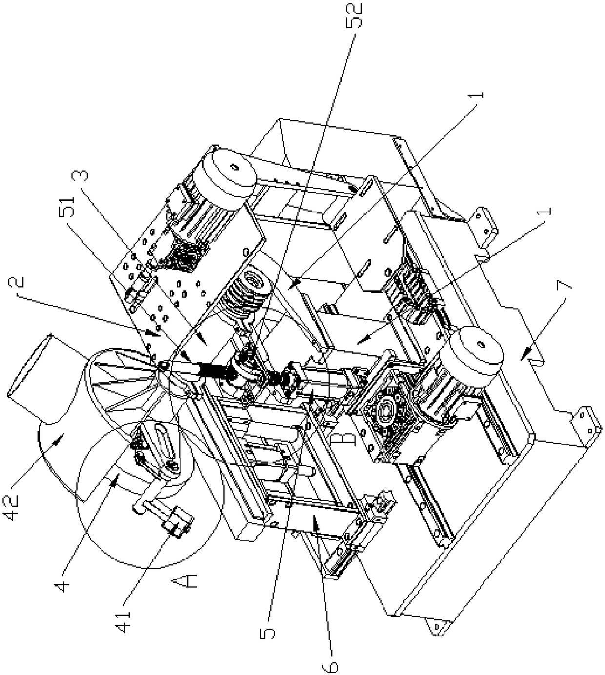
Tableware vertical face filleted corner polisher

A technology of inner fillet and polishing machine, which is applied to surface polishing machine tools, grinding/polishing equipment, manufacturing tools, etc. Low strength, reliable and accurate positioning, and improved stability

Pending Publication Date: 2019-02-22
TIANJIN TTX GROUP
View PDF0 Cites 0 Cited by
  • Summary
  • Abstract
  • Description
  • Claims
  • Application Information

AI Technical Summary

Problems solved by technology

[0002] In the process of forming tableware, it needs to go through various processes such as forming, forging, grinding and polishing. After the first polishing, the part needs to be polished twice to improve the brightness. In the process of tableware processing, it needs to be polished many times in many places. At present, the polishing machine can realize the polishing of one position of the tableware. Before that, our company also designed a kind of Multi-station polishing workbench, after the tableware flows down on one workbench, it undergoes multiple polishing, and then is manually transferred to the next workbench to achieve polishing at other positions, or the second polishing process at the same position, the above structure It is mainly aimed at polishing the large rounded corners of the tableware in the flat state. The above-mentioned structural polishing cannot be used for the inner rounded corners of the vertical surface. In the current operation method, the operator fixes multiple tableware on a fixture, and then the operator takes Polishing on the machine, although multiple parts can be polished at one time, but it is troublesome to install and disassemble, time-consuming and laborious, and the work efficiency is still low, and the quality of polishing also has certain errors due to differences in the level of operators

Method used


Image

  • Tableware vertical face filleted corner polisher
  • Tableware vertical face filleted corner polisher
  • Tableware vertical face filleted corner polisher

Examples


Embodiment Construction

[0023] It should be noted that, in the case of no conflict, the embodiments of the present invention and the features in the embodiments can be combined with each other.

[0024] In describing the present invention, it should be understood that the terms "center", "longitudinal", "transverse", "upper", "lower", "front", "rear", "left", "right", " The orientations or positional relationships indicated by "vertical", "horizontal", "top", "bottom", "inner" and "outer" are based on the orientations or positional relationships shown in the drawings, and are only for the convenience of describing the present invention and Simplified descriptions, rather than indicating or implying that the device or element referred to must have a particular orientation, be constructed and operate in a particular orientation, and thus should not be construed as limiting the invention. In addition, the terms "first", "second", etc. are used for descriptive purposes only, and should not be understood ...


PUM


Abstract

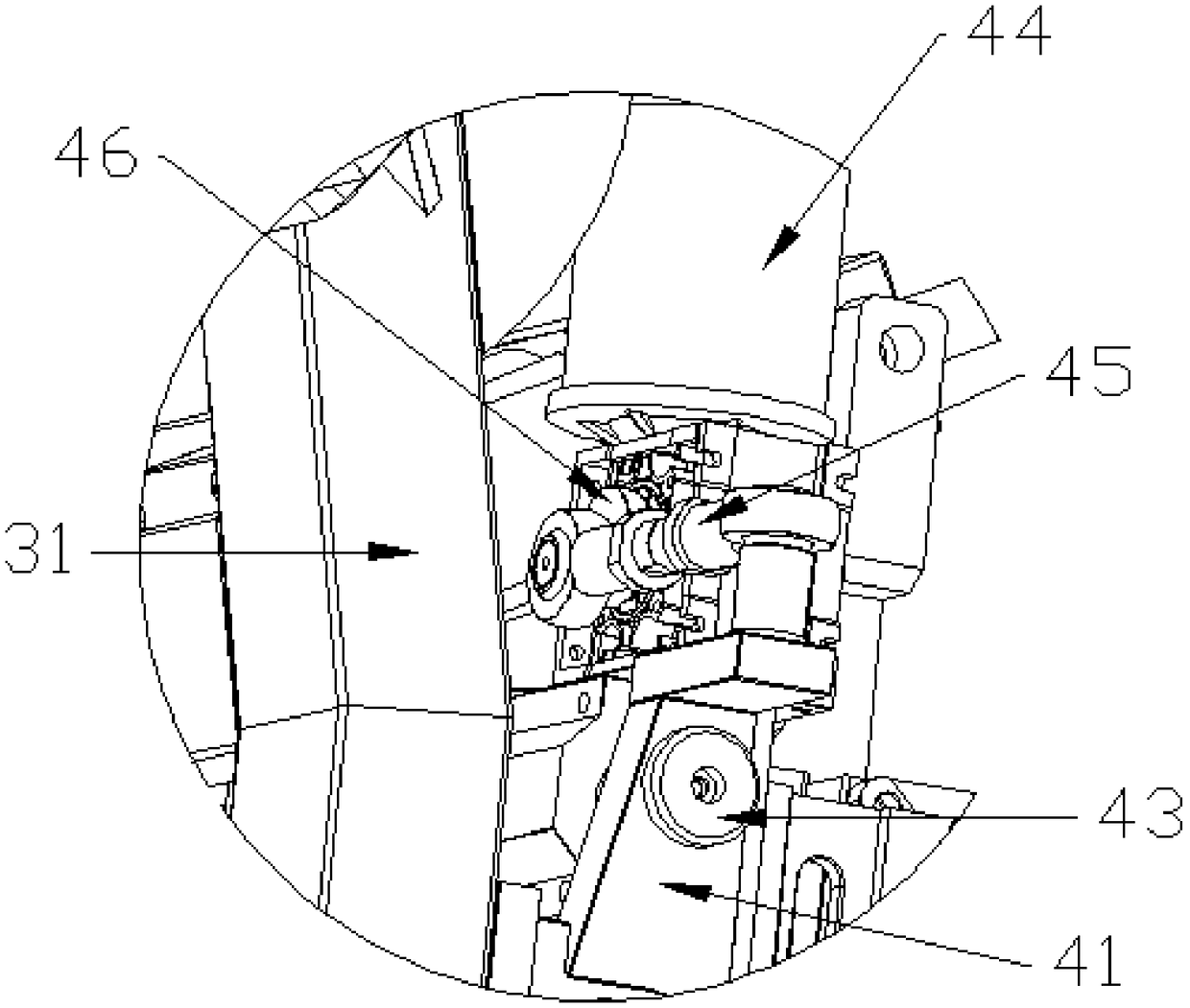
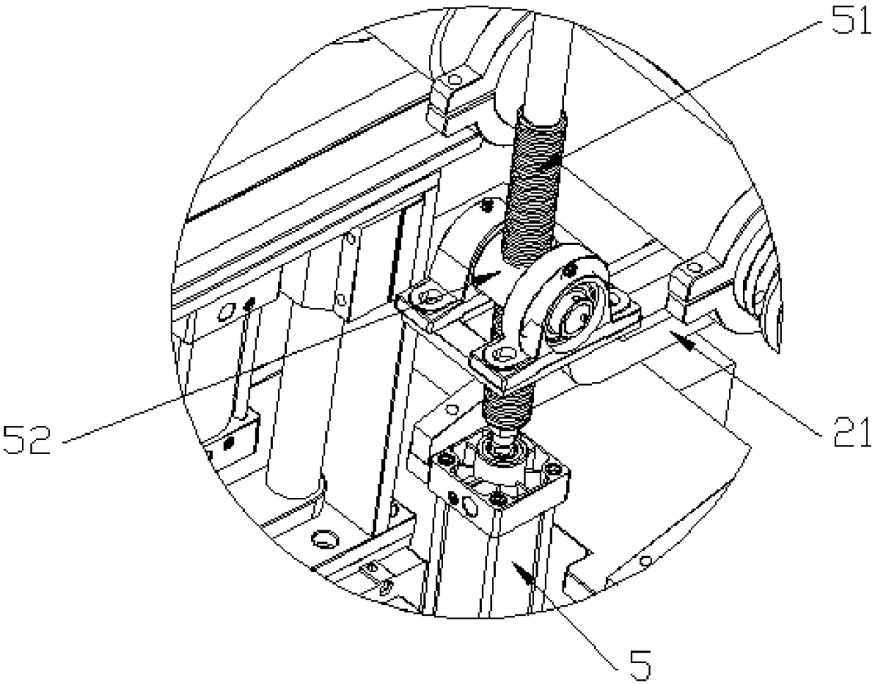
The invention provides a tableware vertical face filleted corner polisher, and belongs to the field of polishing equipment. The tableware vertical face filleted corner polisher comprises a supportingframe, a fixed assembly, a swing assembly and a driving shaft. One end of the swing assembly is hinged to the supporting frame, and the other end of the swing assembly is connected with a force outputshaft of a swing cylinder. The end, away from the force output shaft, of the swing cylinder is hinged to the supporting frame. The driving shaft is rotationally connected relative to the swing assembly. A polishing wheel is fixedly arranged at the end, away from the swing assembly, of the driving shaft. The polishing wheel is arranged over the fixed assembly. The swing assembly comprises an upperplate and a lower plate. The driving shaft is fixedly arranged on the upper plate. The upper plate and the lower plate are in sliding connection, and the sliding direction is parallel to the axis ofthe driving shaft. According to the tableware vertical face filleted corner polisher, tableware vertical face filleted corners can be polished, the automation degree is high, the work efficiency is greatly improved, and the labor intensity is reduced.

Description

technical field [0001] The invention belongs to the field of polishing equipment, and relates to a tableware vertical inner fillet polishing machine. Background technique [0002] In the process of forming tableware, it needs to go through various processes such as forming, forging, grinding and polishing. After the first polishing, the part needs to be polished twice to improve the brightness. In the process of tableware processing, it needs to be polished many times in many places. At present, the polishing machine can realize the polishing of one position of the tableware. Before that, our company also designed a kind of Multi-station polishing workbench, after the tableware flows down on one workbench, it undergoes multiple polishing, and then is manually transferred to the next workbench to achieve polishing at other positions, or the second polishing process at the same position, the above structure It is mainly aimed at polishing the large rounded corners of the tabl...

Claims


Application Information

Patent Timeline
Patent Type & Authority Applications(China)
IPC IPC(8): B24B29/02B24B41/06B24B41/02B24B41/00
CPCB24B29/02B24B41/00B24B41/02B24B41/06
Inventor 田捷才
Owner TIANJIN TTX GROUP
Why Eureka
Try Eureka