Limiting structure and pneumatic executing mechanism with same

A technology of pneumatic actuators and limit structures, applied in the field of control, can solve problems such as piston position changes, jitter, and difficult guarantees

Inactive Publication Date: 2019-02-19
GUODIAN ENVIRONMENTAL PROTECTION RES INST CO LTD
View PDF3 Cites 0 Cited by
  • Summary
  • Abstract
  • Description
  • Claims
  • Application Information

AI Technical Summary

Problems solved by technology

Theoretically, after the air pressure on both sides of the piston of the pneumatic actuator is stable, the piston will not shake theoretically, but it is really difficult to guarantee in practical applications.
Due to problems such as the temperature on both sides of the piston, it is likely to cause a change in air pressure, which in turn leads to a change in the position of the piston, resulting in jitter, which greatly affects the performance of the pneumatic actuator.

Method used


Image

  • Limiting structure and pneumatic executing mechanism with same
  • Limiting structure and pneumatic executing mechanism with same
  • Limiting structure and pneumatic executing mechanism with same

Examples


Embodiment Construction

[0026] In order to enable those skilled in the art to better understand the technical solutions of the present invention, the present invention will be further described in detail below in conjunction with the accompanying drawings and specific embodiments.

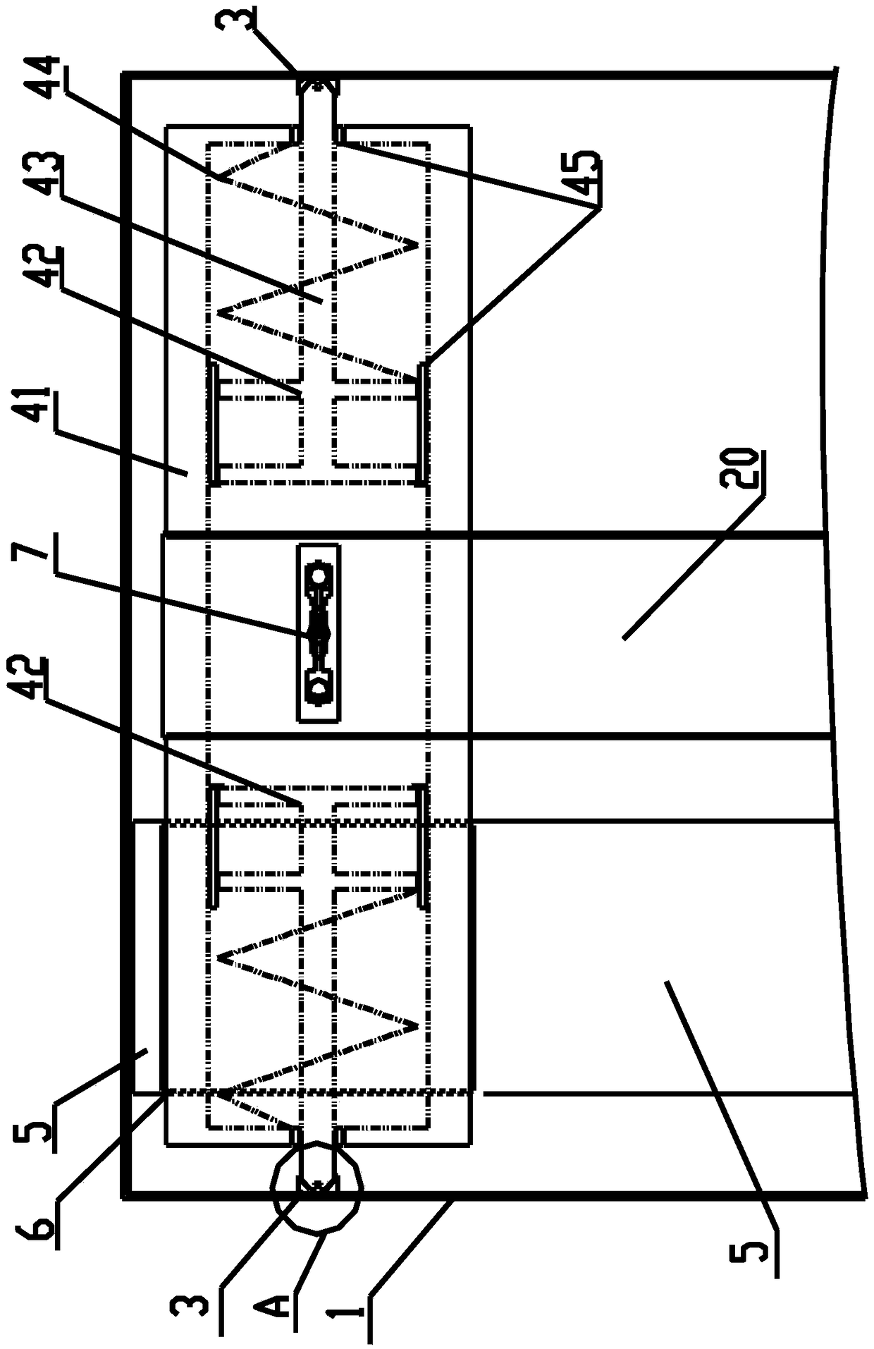
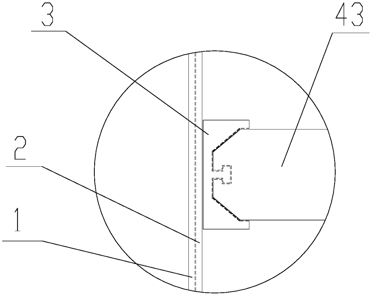
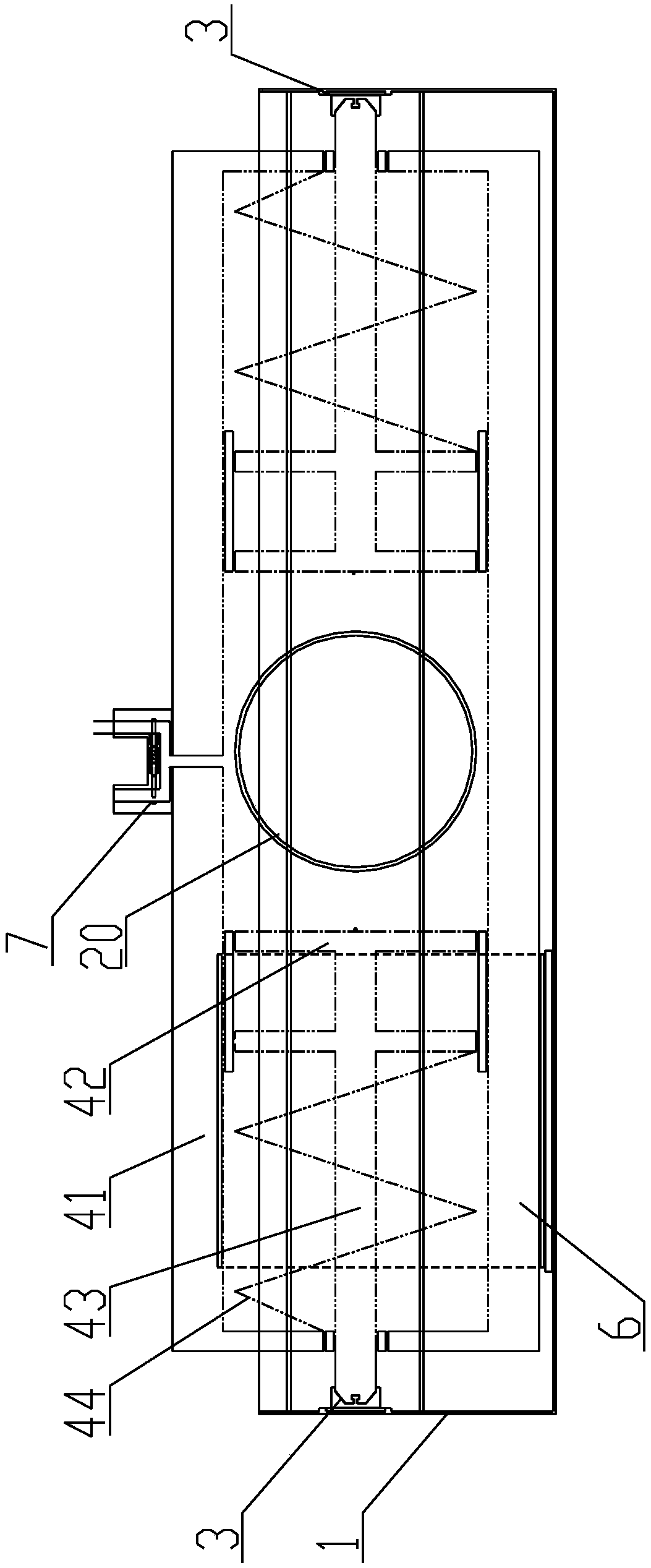
[0027] Please refer to figure 1 , figure 1 It is a structural schematic diagram of the assembly of a position-limiting structure and an actuating rod in the present invention; figure 2 for figure 1 The enlarged schematic diagram of A; image 3 for figure 1 another view of .

[0028] The pneumatic actuator includes an executive body. There are fluid passages and pistons inside the executive body. Valves are arranged on the fluid passages. The air source drives the piston to reciprocate between the first position and the second position. When the piston is at the first position, the interior of the executive body When the piston is in the second position, the valve inside the execution body is closed to meet the worki...


PUM


Abstract

The invention discloses a limiting structure and a pneumatic executing mechanism with the limiting structure. When the limiting structure is used, a second friction piece can be mounted at the outer end of an acting rod, and a main frame is correspondingly mounted on an executing body of the pneumatic executing mechanism or other bodies fixed relative to the use environment. In the motion processof the acting rod, a driving mode controls friction force between a first friction piece and the second friction piece to be small as much as possible (zero optimally), no acting force is applied to the acting rod to the best, and the normal action of the acting rod is prevented from being influenced. At this moment, the second friction piece can move along with the acting rod; when air pressure on the two sides of a piston moves to a designated spot, a driving module controls the friction force between the first friction piece and the second friction piece to be fast increased to a preset value, the second friction piece cannot relatively move relative to the first friction piece, and then the position of the piston is locked; and the phenomenon that the piston in the prior art shakes after moving in place is eliminated, and the work reliability of the pneumatic executing mechanism can be greatly improved.

Description

technical field [0001] The invention relates to the technical field of control, in particular to a position-limiting structure and a pneumatic actuator with the position-limiting structure. Background technique [0002] Pneumatic actuator is a device that uses air source to drive on or off, and the opposite action is reset by spring. The types of pneumatic actuators are: film type, piston type, fork type and rack and pinion type. [0003] Among them, the piston pneumatic actuator has the characteristics of long stroke and is widely used. The pneumatic actuator drives the piston to move left and right through the air source to open or close the valve. Theoretically, after the air pressure on both sides of the piston of the pneumatic actuator is stable, the piston will not shake theoretically, but it is really difficult to guarantee it in practical applications. Due to problems such as the temperature on both sides of the piston, it is likely to cause a change in the air pr...

Claims


Application Information

Patent Timeline
IPC IPC(8): F16K31/122F16K31/06
CPCF16K31/0675F16K31/1221
Inventor 邱祥哲邱子航孙天凯任宇哲王立文邱祥民孙尊强
Owner GUODIAN ENVIRONMENTAL PROTECTION RES INST CO LTD
Why Eureka
Try Eureka