S-Shaped sand blasting passage unit

A technology of jet flow and sand, which is applied to locomotives and other directions, can solve the problems of high pressure requirements of air compressors, many parts, and easy blockage of sand

Inactive Publication Date: 2019-02-19
华伍轨道交通装备(上海)有限责任公司
View PDF8 Cites 0 Cited by
  • Summary
  • Abstract
  • Description
  • Claims
  • Application Information

AI Technical Summary

Problems solved by technology

[0004] This type of sand injection flow channel has certain disadvantages: the air flow passes through many parts, and the sand carried by the air flow is easily blocked in the sand spreading pipe and sand discharge pipe, making it difficult to spread sand and requiring high pressure on the air compressor. At the same time, the airtightness requirements for sand boxes, sand valves and pipelines are relatively high

Method used


Image

  • S-Shaped sand blasting passage unit
  • S-Shaped sand blasting passage unit
  • S-Shaped sand blasting passage unit

Examples


Embodiment Construction

[0021] The present invention will be further described below in conjunction with accompanying drawing:

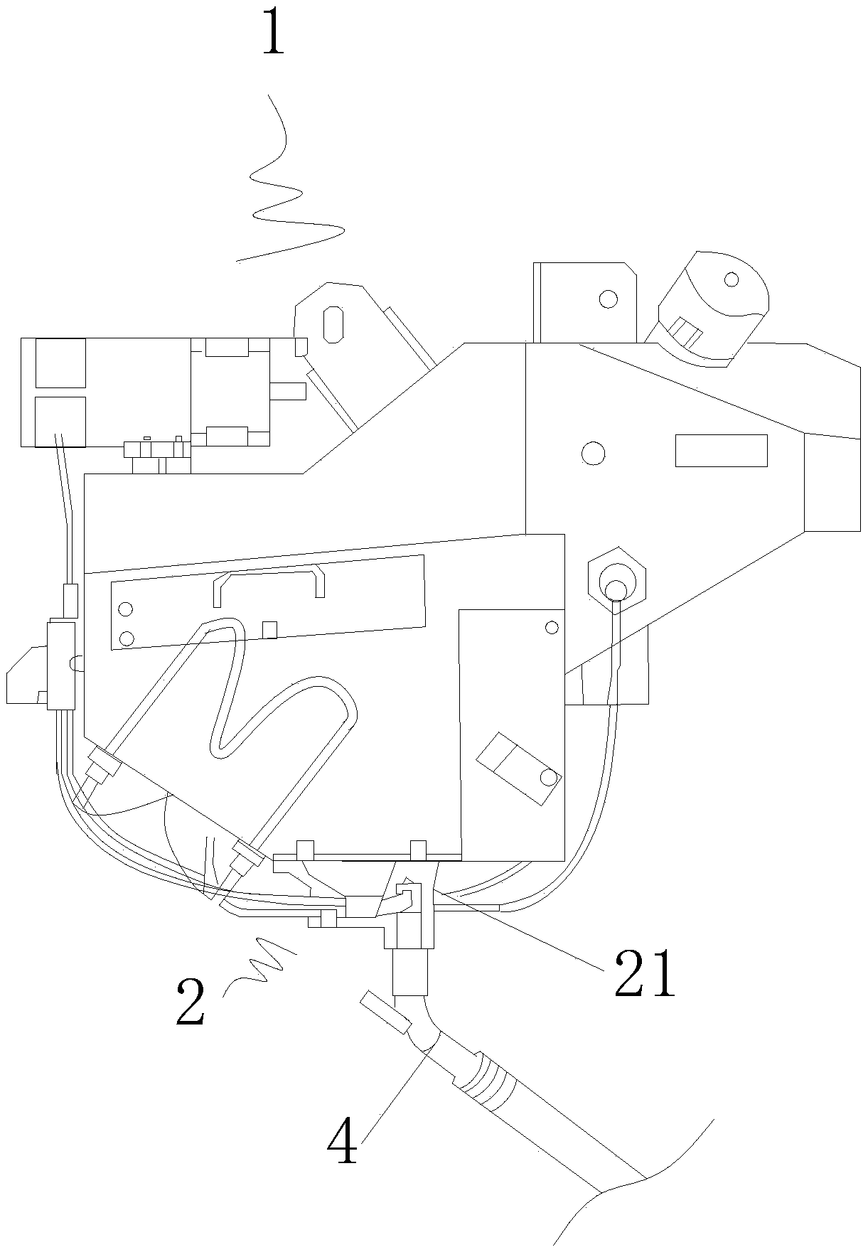
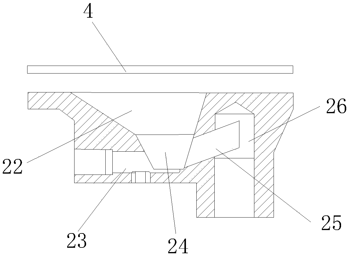
[0022] Such as Figure 1-3 The shown S-shaped sand blasting flow channel includes a sand-spraying device main body 1 and an S-shaped sand-blasting flow channel 2. The S-shaped sand-blasting flow channel 2 is located at the bottom of the sand-sprinkling device main body 1. The sand flow channel 2 includes a sand spreading valve 21, the top of the sand spreading valve 21 is equipped with a flow limiting plate 3, and the sand spreading valve 21 is located at the bottom of the flow limiting plate 3 and is provided with a funnel flow channel 22, and the funnel flow The cross section of the channel 22 is rectangular, and the bottom of the funnel flow channel 22 is provided with a cavity 24, and one side of the bottom of the cavity 24 is provided with a straight air duct 23 horizontally, and the other side of the cavity 24 The side is provided with a rectangular flow channel 25 a...


PUM


Abstract

The invention discloses an S-shaped sand blasting passage unit, comprising a sand scatterer body and an S-shaped sand blasting passage; the S-shaped sand blasting passage is arranged at the bottom ofthe sand scatterer body and includes a sand scattering valve; a flow limiting plate is mounted at the top of the sand scattering valve; the sand scattering valve is provided with a funnel passage at the bottom of the flow limiting plate; the cross section of the funnel passage is rectangular; the bottom of the funnel passage is provided with a cavity; a direct draught pipe is transversely arrangedon one side of the bottom of the cavity; a rectangular passage inclined is arranged on the other side of the cavity; the side, far away from the direct draught pipe, of the rectangular passage is provided with a downward vertical passage; the bottom of the downward vertical passage is provided with a Y-shaped draught pipe; according to an S-shaped sea of a water pipe, sand stay still when not scattered; the S-shaped passage acts as a sand blocking plug; the sand in the S-shaped passage is still; upon sand scattering, the sand can be scattered along the smooth S-shaped sand blasting passage inquick and controllable manner under positive and negative suction action of compressed air from the direct draught pipe and the Y-shaped draught pipe.

Description

technical field [0001] The invention relates to a rail transit braking system, in particular to an S-shaped sand injection channel. technical background [0002] The sand spreading device for rail vehicles is used to improve the adhesion coefficient of the wheel and increase the braking efficiency. The sand spreading device is mainly composed of a sand box, a sand spreading valve and a sand spreading pipe. The sand spreading valve is mainly composed of a sand injection flow channel and an air induction pipe. The sand spreading device mainly has two structural forms: gravity type and differential pressure type. Compared with the gravity sand spreading device, the differential pressure sand spreading device is easy to control the amount of sand and has the function of drying sand, but it is difficult to maintain and has a high failure rate. [0003] At present, most of the sand spreading devices use the differential pressure type, and its sand injection flow path is relativel...

Claims


Application Information

Patent Timeline
IPC IPC(8): B61C15/10
CPCB61C15/10B61C15/102
Inventor 查小翔周汉国李毅李常品
Owner 华伍轨道交通装备(上海)有限责任公司
Why Eureka
Try Eureka