
Clamping device of stator blade

A stator vane and clamping device technology, which is applied in the direction of workpiece clamping devices, manufacturing tools, etc., can solve the problems of small clamping end area of ​​the stator vane and the inability to stably and reliably fix the stator vane, so as to achieve a clear design structure and reduce test costs , The effect of low processing cost

Inactive Publication Date: 2019-02-19
AECC SICHUAN GAS TURBINE RES INST
View PDF4 Cites 0 Cited by
  • Summary
  • Abstract
  • Description
  • Claims
  • Application Information

AI Technical Summary

Problems solved by technology

The area of ​​the clamping end of the stator vane is small, and the inside and outside are arc-shaped surfaces. Directly pressing or clamping cannot fix the stator vane stably and reliably.

Method used


Image

  • Clamping device of stator blade

Examples


Embodiment Construction

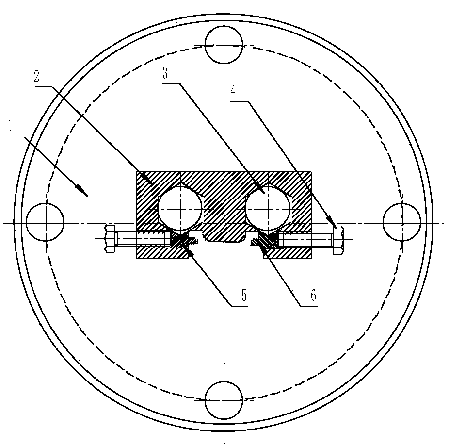
[0014] The present invention passes figure 1 The arc-shaped clamping device of the stator blade shown in the figure realizes stable and reliable installation when the clamping end area of ​​the stator blade is small and arc-shaped.

[0015] The stator blade arc-shaped clamping device of the present invention includes a base 1, a fixed pressing block 2, a pressing bolt 3, an arc-shaped tightening bolt 4, a first arc-shaped tightening block 5, and a second arc-shaped tightening block 6; The base 1 is connected to the fixed pressing block 2 through the pressing bolt 3, the arc-shaped tightening bolt 4 is connected to the fixed pressing block 2 through threads, and the first arc-shaped pressing block 5 and the second arc-shaped pressing block 6 are connected through the arc-shaped Jacking bolt 4 is jacked up and fixed.

[0016] The hold-down bolts 3 are two M8×1 bolts, and the arc-shaped hold-down bolts 4 are four M4 bolts, which are installed and pressed from the side.

[0017]...


PUM


Abstract

The invention discloses a clamping device of a stator blade. The clamping device comprises a fixing assembly and a clamping assembly. The fixing assembly comprises a fixing pressing block, the fixingpressing block is connected with the radial outer end of the stator blade, the portion, connected with the radial outer end of the stator blade, of the fixing pressing block is provided with a uniformarc face, the clamping assembly is used for clamping the stator blade, the clamping assembly comprises a clamping pressing block, the clamping pressing block is connected with the circumferential outer end of the stator blade, and the portion, connected with the circumferential outer end of the stator blade, of the fixing pressing block is provided with a uniform arc face. Stable and reliable installation is achieved on the condition that the clamping end of the stator blade is small in area and is in an arc shape.

Description

technical field [0001] The invention relates to a clamping device for a stator vane, in particular to a clamping device for a stator vane used in an aeroengine vibration test. Background technique [0002] The engine stator blade is a key part of the engine. During the development process, the high cycle fatigue life of the stator blade must be assessed. At present, the most widely used test method is to cut the overall annular stator blade into a single stator blade with crowns on both ends for testing. The size of the stator blade is small, and the clamping part is smaller. The general thickness is about 2mm. Under clamping in a tight way, it will often cause deformation of the blade, thereby changing the mode of the blade itself, thereby changing the distribution of stress, and the test results are not ideal, which affects the analysis and optimization of the results. It is feasible to fix the arc-shaped surface of the stator blade with a relatively large area by designi...

Claims


Application Information

Patent Timeline
Patent Type & Authority Applications(China)
IPC IPC(8): B25B11/00
CPCB25B11/00
Inventor 符顺国代江波罗现强朱靖史庭亭
Owner AECC SICHUAN GAS TURBINE RES INST
Learn More