Shrouded turbine blade damping test device
A turbine blade and test device technology, which is applied to measurement devices, elasticity tests, engine tests, etc., can solve problems such as inability to obtain damping parameters, and achieve the effects of clear design structure, low processing cost, and convenient use.
- Summary
- Abstract
- Description
- Claims
- Application Information
AI Technical Summary
Problems solved by technology
Method used
Image
Examples
Embodiment 1
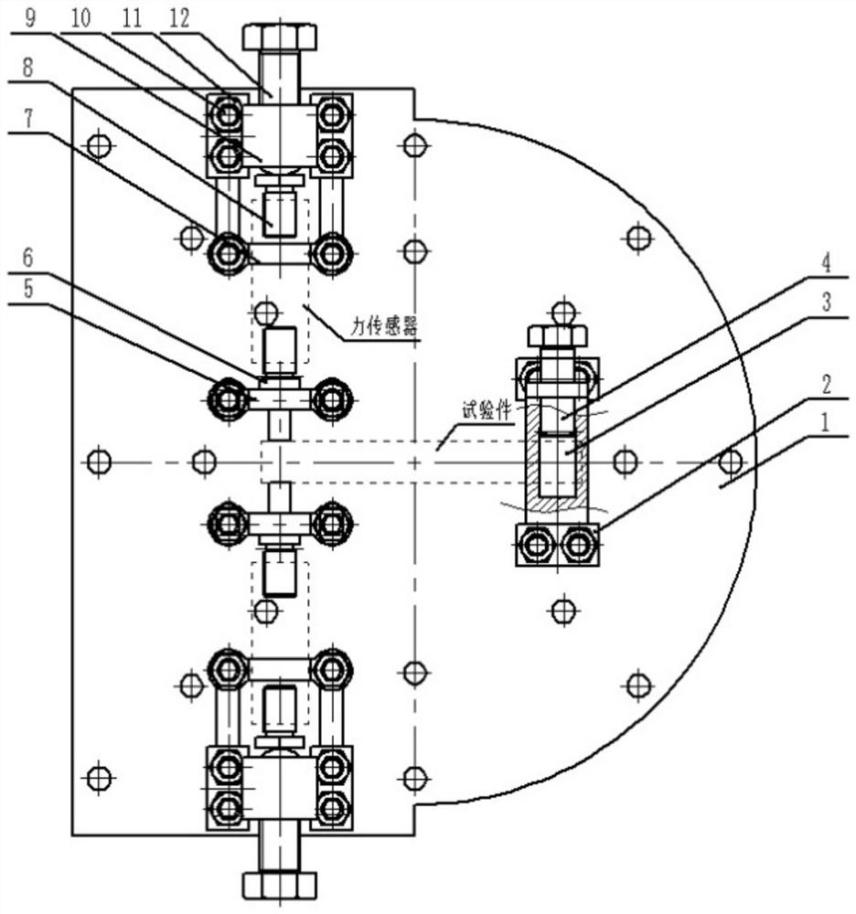
[0018] The tenon clamping assembly and the blade crown loading assembly, the tenon clamping assembly includes the chuck fixing seat, the chuck, the chuck clamping bolt, the fixing bolt and the fixing nut, the chuck clamps the tenon of the turbine blade, and the chuck is placed on the chuck fixing seat In the middle, the collet tightening bolt is tightened to fix the collet, and the collet fixing seat is fastened on the base through the fixing bolt and the fixing nut; the shroud loading assembly is used for loading the turbine blade shroud, and the shroud loading assembly includes the front support , loading block, sensor support, bearing block, rear support, fixing bolts, fixing nuts, loading jacking bolts, the blade shroud loading assembly is a symmetrical structure about the blade shroud, on the same straight line and perpendicular to the blade body.
[0019] In the above test device, the middle section of the loading block has a square structure and passes through the square...
Embodiment 2
[0024] The present invention designs a turbine blade damping test device with a shroud figure 1 , to realize the installation scheme of measuring the damping parameters of shrouded turbine blades under the extrusion of different clamping forces.
[0025] The crowned turbine blade damping test device of the present invention includes a base (1), a chuck holder (2), a chuck (3), a chuck jacking bolt (4), a front support (5), a loading block (6), Sensor support (7), bearing block (8), rear support (9), fixing bolts (10), fixing nuts (11), loading jacking bolts (12); the chuck fixing seat (2), front The support (5), the sensor support (7), the rear support (9) and the base (1) are connected by fixing bolts (10) and fixing nuts (11), and the chuck (3) is fixed on the on the chuck holder (2). The loading block (6) is connected together with the front support (5). Loading jacking bolts (12) are connected together with rear support (9).
[0026] The front support (5), the loading ...
PUM
 Abstract
Description
Claims
Application Information
 - Generate Ideas
- Intellectual Property
- Life Sciences
- Materials
- Tech Scout
- Unparalleled Data Quality
- Higher Quality Content
- 60% Fewer Hallucinations
Browse by: Latest US Patents, China's latest patents, Technical Efficacy Thesaurus, Application Domain, Technology Topic, Popular Technical Reports.
© 2025 PatSnap. All rights reserved.Legal|Privacy policy|Modern Slavery Act Transparency Statement|Sitemap|About US| Contact US: help@patsnap.com

