Automatic metal surface processing device

An automatic processing, metal surface technology, applied in metal processing equipment, grinding devices, grinding/polishing safety devices, etc., can solve problems such as inability to identify, time-consuming and labor-intensive, and low processing efficiency, saving materials and ensuring imaging. Precision and accuracy, the effect of improving production efficiency

Inactive Publication Date: 2019-02-19
苏州丰川电子科技有限公司
View PDF13 Cites 1 Cited by
  • Summary
  • Abstract
  • Description
  • Claims
  • Application Information

AI Technical Summary

Problems solved by technology

However, on each workpiece, the area that needs to be polished is often only in a local area, because the grinding device cannot identify the local area that needs to be polished, and the local grinding can only be achieved through comprehensive grinding, which is time-consuming and labor-intensive, and the processing efficiency is low.

Method used


Image

  • Automatic metal surface processing device
  • Automatic metal surface processing device
  • Automatic metal surface processing device

Examples


Embodiment 1

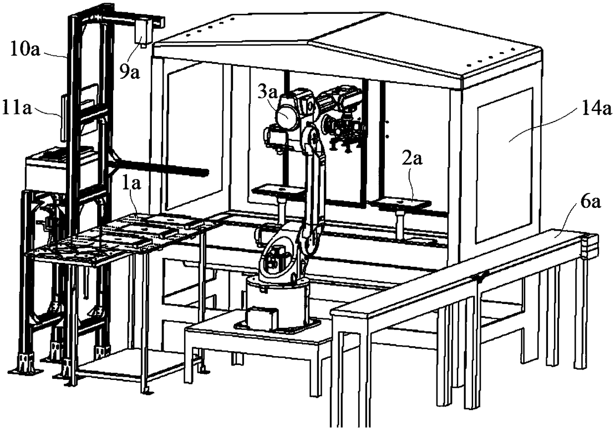
[0039] Embodiment 1: a kind of metal surface automatic processing device, comprises feeding support 1a, grinding support 2a, some mechanical arms 3a, grinding head 4a and material delivery clamp 5a, described grinding head 4a and material delivery clamp 5a are respectively connected with The end nodes of the mechanical arm 3a are installed and connected, and the feeding support 1a and the grinding support 2a are respectively arranged along the circumferential direction of the mechanical arm 3a;

[0040] Described loading support 1a comprises support 7a and the loading table 8a that is installed on the support 7a, and described loading table 8a has an imaging mechanism 9a on the side opposite to mechanical arm 3a, and this imaging mechanism 9a is installed on a The upper end of the mounting frame 10a is located above the loading table 8a, and the grinding support 2a includes a base 12a and several grinding tables 13a connected to the upper surface of the base 12a;

[0041] The ...

Embodiment 2

[0050] Embodiment 2: a kind of metal surface automatic processing device, comprises feeding support 1a, grinding support 2a, some mechanical arms 3a, grinding head 4a and material delivery clamp 5a, described grinding head 4a and material delivery clamp 5a are respectively connected with The end nodes of the mechanical arm 3a are installed and connected, and the feeding support 1a and the grinding support 2a are respectively arranged along the circumferential direction of the mechanical arm 3a;

[0051] Described loading support 1a comprises support 7a and the loading table 8a that is installed on the support 7a, and described loading table 8a has an imaging mechanism 9a on the side opposite to mechanical arm 3a, and this imaging mechanism 9a is installed on a The upper end of the mounting frame 10a is located above the loading table 8a, and the grinding support 2a includes a base 12a and several grinding tables 13a connected to the upper surface of the base 12a;

[0052] The ...


PUM


Abstract

The invention discloses an automatic metal surface processing device which comprises a feeding support, a polishing support, a plurality of mechanical arms, a polishing head an a transporting clamp, wherein the polishing head an the transporting clamp are in erection joint with the tail nodes of the mechanical arms; the feeding support and the polishing support are arranged in the circumferentialdirection of the mechanical arms; the feeding support comprises a bracket and a feeding table mounted on the bracket; the polishing head further comprises an inner shell, an outer shell, a core body and a rotary head; the inner shell is in the outer shell; the core body is rotatably arranged in the inner shell; and the central axis of the outer wall cylindrical surface of the inner shell and the central axis of the inner wall cylindrical surface of the inner shell are in parallel and do not coincide. According to the automatic metal surface processing device, the inner and outer shells are combined with the core body, the structure is skillful, the air enters the inner shell through a first cavity to blow a driving blade, the driving blade drives the core body to rotate, the air is then discharged out through a second cavity, and the core body rotates to drive the rotary head to rotate so as to realize automatic polishing. The automatic metal surface processing device is simple in structure and convenient to use.

Description

technical field [0001] The invention relates to an automatic metal surface processing device, which belongs to the technical field of processing precision parts of electronic products. Background technique [0002] At present, most of the appearance structural parts / accessories of mobile phones and laptops on the market are made of metal materials. The forming of metal materials mainly includes aluminum extrusion, die-casting, forging and other methods. No matter which forming method is used, CNC machining centers are required for processing after forming. Due to the existence of poor appearance such as knife marks and scratches in the CNC machining process, a series of appearance retreatments such as passivation, grinding and polishing, spraying, and anodic oxidation must be carried out on the workpiece. However, on each workpiece, the area that needs to be polished is often only in a local area, because the grinding device cannot identify the local area that needs to be po...

Claims


Application Information

Patent Timeline
Patent Type & Authority Applications(China)
IPC IPC(8): B24B37/00B24B37/34B24B55/00
CPCB24B37/00B24B37/34B24B55/00
Inventor 赵长亮周士升蒋燕詹淳崵
Owner 苏州丰川电子科技有限公司
Why Eureka
Try Eureka