
A high-bandwidth radio frequency signal arrival time measurement device and method

A technology of radio frequency signal and time of arrival, which is applied in the direction of electromagnetic transmitters, electrical components, electromagnetic wave transmission systems, etc., can solve the problems of low noise radio frequency signal source, poor performance of high frequency band, impact on resolution, etc., and achieve high precision time measurement High resolution, small external noise, and high time resolution

Active Publication Date: 2020-11-06
SHANGHAI INST OF APPLIED PHYSICS - CHINESE ACAD OF SCI
View PDF6 Cites 0 Cited by
  • Summary
  • Abstract
  • Description
  • Claims
  • Application Information

AI Technical Summary

Problems solved by technology

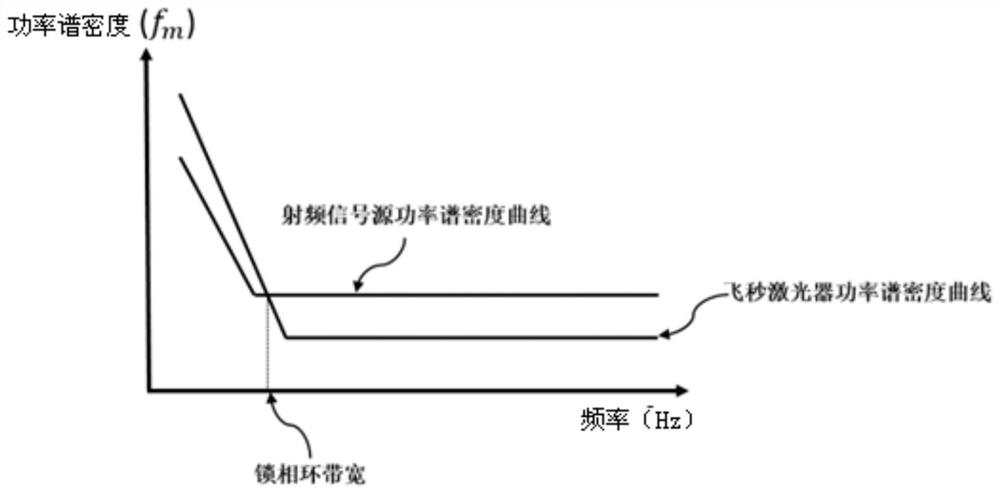
[0021] Since low-noise RF signal sources perform better at low frequencies and poorer at high frequencies, the performance limitations of low-noise RF signal sources will affect the final resolution of the time-of-arrival measurement of the measured signal; on the other hand, analog-to-digital conversion The clock jitter performance of the input clock to the device will also affect the resolution of the time-of-arrival measurement of the signal under test
[0022] In summary, the shortcoming of the prior art is that it is necessary to provide a radio frequency reference signal source with low noise performance, the noise performance of the reference signal source will limit the measurement resolution of the time of arrival of the radio frequency signal to be tested, and the existing reference signal source in the low frequency band ( 1Hz to 1KHz) has good noise performance, and the high frequency band (1KHz to 10MHz) has poor performance

Method used


Image

  • A high-bandwidth radio frequency signal arrival time measurement device and method
  • A high-bandwidth radio frequency signal arrival time measurement device and method
  • A high-bandwidth radio frequency signal arrival time measurement device and method

Examples


Embodiment Construction

[0040] Below, in conjunction with the accompanying drawings, preferred embodiments of the present invention are given and described in detail, so that the functions and features of the present invention can be better understood.

[0041] Such as Figure 4 Shown is a time-of-arrival measurement device for a high-bandwidth radio frequency signal according to an embodiment of the present invention, which is based on an electro-optic modulation scheme and is used to detect a time-of-arrival of a radio frequency signal to be measured, including an electro-optic modulator 1, a reference signal source, a photoelectric detector device 4, optical delay line 5 and phase shifter 6. In this embodiment, the electro-optic modulator 1 is an electro-optic intensity modulator, its function is to modulate the amplitude of the laser pulse array, it has an optical signal input end 11, an electrical signal input end 12 and an optical signal output end 13, The optical signal input end 11 is connec...


PUM


Abstract

The invention provides a device for measuring the time of arrival of a high-bandwidth radio frequency signal. The device comprises the following parts: an electrooptical modulator connected with a radio frequency signal to be measured; a reference signal source comprising a femtosecond laser device and a low-noise radio frequency signal source, wherein the femtosecond laser device is connected with the electrooptical modulator, and is located in a phase-locked loop, and the low-noise radio frequency signal source is connected to the input end of the phase-locked loop; and a photoelectric detector connected with the electrooptical modulator. According to the device for measuring the time of arrival of the high-bandwidth radio frequency signal, which is disclosed by the invention, the extremely low-noise femtosecond laser device is locked onto the low-noise radio frequency source through a phase-locked loop technology; the reference signal source with excellent noise performance is modulated through the electrooptical modulator according to the radio frequency signal to be measured; time of arrival information can be demodulated only by measuring an amplitude value of the modulated signal, so that high-precision time measurement resolution is realized; and furthermore, a laser pulse string is little interfered and affected by the outside in a transmission process, so that introduced external noise is lower.

Description

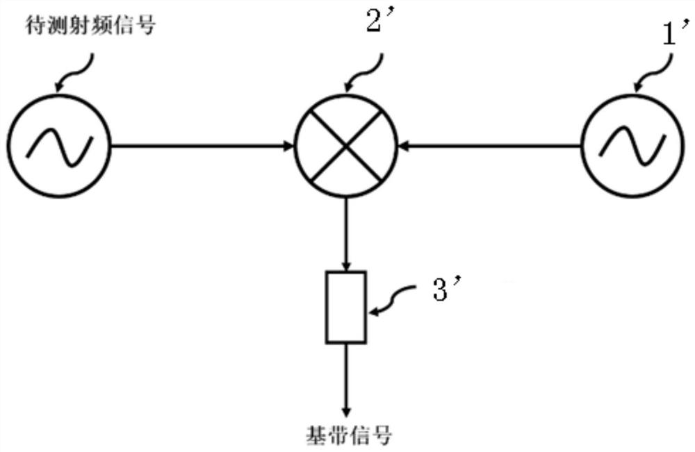
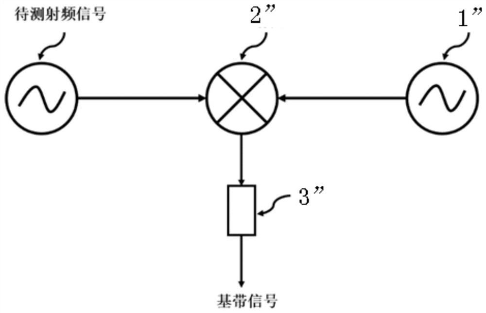
technical field [0001] The invention relates to a time measurement method, in particular to a method for measuring the arrival time of a high-bandwidth radio frequency signal. Background technique [0002] With the development of science and technology, especially in the field of accelerators (synchrotron radiation sources, free electron lasers, linear colliders, etc.), phased array radars and radio telescope clusters, etc., the requirements for the resolution of signal arrival time measurement are increasing. [0003] There are two main methods for measuring the time of arrival of signals at present. [0004] one such as figure 1 As shown, the RF signal to be tested is mixed with another known same-frequency low-noise RF reference signal source 1' through a mixer 2', and the sum frequency signal is filtered out through a low-pass filter 3', leaving only the difference The frequency signal, that is, the baseband signal, the arrival time signal of the RF signal to be tested...

Claims


Application Information

Patent Timeline
Patent Type & Authority Patents(China)
IPC IPC(8): H04B10/079H04B10/54H04B10/556
CPCH04B10/0795H04B10/541H04B10/5561
Inventor 汪金国刘波
Owner SHANGHAI INST OF APPLIED PHYSICS - CHINESE ACAD OF SCI
Learn More