
A start-up circuit of a bandgap reference voltage source

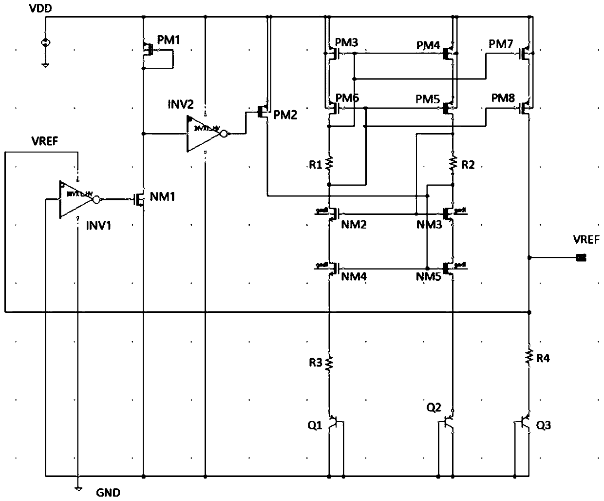
A reference voltage source and start-up circuit technology, applied in the direction of adjusting electrical variables, instruments, control/regulation systems, etc., can solve the problems of inapplicable ultra-low power consumption, occupation, large chip area, etc., to simplify complex designs and improve circuits. The effect of reliability, ultra-low power application

Active Publication Date: 2020-07-24
安徽矽磊电子科技有限公司
View PDF7 Cites 0 Cited by
  • Summary
  • Abstract
  • Description
  • Claims
  • Application Information

AI Technical Summary

Problems solved by technology

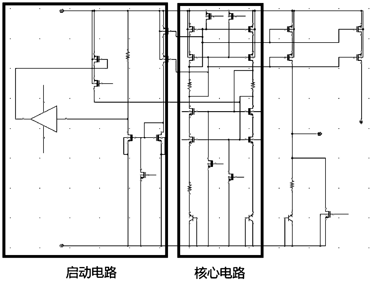
[0004] The traditional bandgap reference voltage source adopts the technique of canceling the positive temperature coefficient and the negative temperature coefficient, which can generate an output voltage that is constant with the power supply voltage and temperature. It has been widely used in various analog and mixed signal products. This circuit has full The advantages of integration, low power consumption, and simple and convenient implementation; but because the circuit has two working states of normal working current and zero current, a startup circuit is needed to ensure the normal operation of the circuit
But the traditional start-up circuit often requires quiescent working current, so it is not suitable for ultra-low power consumption applications; and in order to achieve a very low current to ensure the start-up circuit works, it often needs a large resistor and transistor to achieve, which will occupy large chip area

Method used


Image

  • A start-up circuit of a bandgap reference voltage source
  • A start-up circuit of a bandgap reference voltage source

Examples


Embodiment Construction

[0019] In order to make the purpose, technical solution and advantages of the present invention more clear, the embodiments of the present invention will be described in detail below in conjunction with the accompanying drawings. It should be noted that, in the case of no conflict, the embodiments in the present application and the features in the embodiments can be combined arbitrarily with each other.

[0020] figure 1 Shown is a traditional bandgap reference voltage circuit, which is mainly composed of two parts: the core circuit and the start-up circuit, in which the core circuit uses resistors and transistors to generate two voltages with positive temperature coefficient and negative temperature coefficient respectively and add them together The output reference voltage is obtained, so that the positive temperature coefficient and the negative temperature coefficient are completely offset, and the output reference voltage has nothing to do with temperature; a current mirr...


PUM


Abstract

The invention provides a starting circuit of a band-gap reference voltage source. The starting circuit is characterized by comprising a first phase inverter, a second phase inverter, a first transistor, a second transistor and a third transistor, wherein the positive end of a power supply of the first phase inverter is connected with the output voltage of the band-gap reference voltage source, theinput end of the first phase inverter is grounded, the output end of the first phase inverter is connected with the control end of the first transistor, the input end of the first transistor is connected with the output end of the second transistor and the input end of the second phase inverter, and the output end of the first transistor is grounded; the input end of the second transistor, the input end of the third transistor and the positive end of a power supply of the second phase inverter are connected with supply voltage (VDD); the control end of the second transistor is further connected with the output end, and the control end of the third transistor is connected with the output end of the second phase inverter; the drain electrode of the third transistor serves as a starting voltage output end. The starting circuit adopts a full-digital mode without any static power consumption, the starting circuit is not affected by the supply voltage, the structure is simple, and a required chip area is small.

Description

technical field [0001] The invention relates to the field of power circuits, in particular to a starting circuit of a bandgap reference voltage source. Background technique [0002] The domestic mobile phone market is booming. According to a survey by the High-tech Lithium Battery Industry Research Institute, China’s mobile phone shipments reached 1.25 billion units in 2012, and the mobile phone lithium battery market reached 23.2 billion yuan (including PACK). Lithium-ion batteries are basically used in mobile phones. According to the requirements of different electronic products, they can be made into flat rectangle, cylinder, rectangle and button type, etc., and several batteries can be connected in series and parallel to form a battery pack. The rated voltage of lithium-ion batteries is generally 3.7V due to changes in materials, while that of lithium iron phosphate (hereinafter referred to as iron phosphorus) positive electrode is 3.2V. The termination charging voltage...

Claims


Application Information

Patent Timeline
Patent Type & Authority Patents(China)
IPC IPC(8): G05F3/26
CPCG05F3/267
Inventor 王晗
Owner 安徽矽磊电子科技有限公司
Learn More