Engineering machinery test bench

A technology of construction machinery and test bench, which is applied in the field of construction machinery, can solve the problems of inability to detect loads and affect the safety and stability of construction machinery, and achieve the effect of strong controllability and easy research and analysis

Inactive Publication Date: 2019-02-15
常州华睿新能源汽车发展有限公司
View PDF0 Cites 1 Cited by
  • Summary
  • Abstract
  • Description
  • Claims
  • Application Information

AI Technical Summary

Problems solved by technology

[0003] In order to overcome the problem that the test device existing in the prior art is relatively simple and cannot detect loads in all directions of the frame, which seriously affects the safety and stability of construction machinery, the invention provides a construction machinery test bench, which is characterized in that It includes construction machinery frame, frame rotation device and four supports, the frame rotation device and support are installed on the construction machinery frame, the support is placed horizontally, and four hydraulic drivers, four Force detection device, four ball connection devices, the lower part of the rotating device is equipped with an intermediate support seat

Method used


Image

  • Engineering machinery test bench
  • Engineering machinery test bench

Examples


Embodiment 1

[0016] Embodiment 1: Test when simulating three-leg support

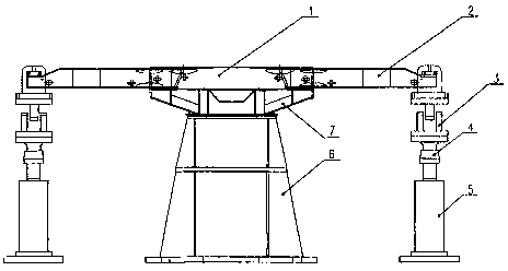
[0017] During the lifting operation of construction machinery, there may be a state supported by three outriggers, that is, one of the vertical outriggers is not stressed or called suspended. At this time, the supporting reaction force of the other three vertical outriggers or Through theoretical calculation, the support reaction force of the other three vertical legs is obtained.

[0018] During the test, first assemble the tested engineering machinery vehicle frame 1 and support 2, hydraulic drive 5, force detection device 4 and related test tooling according to the content of the present invention. On the test bench, the corresponding load applied to the vertical leg is simulated by the hydraulic driver 5 to test the parameters such as strain and displacement at the relevant positions of the construction machine frame 1 and the bracket 2 .

Embodiment 2

[0019] Embodiment 2: Simulation test and fatigue test when simulating the rotation of the suspended heavy object

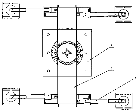
[0020] During the lifting operation of construction machinery, the rotation of the heavy object is a common working condition. The change of the support reaction force on the outriggers is reflected in the change of the support reaction force on the four outriggers with the position of the heavy object. keep changing. At this time, the change of the support reaction force of the four vertical legs can be obtained through actual measurement of the support reaction force of the four vertical legs or through theoretical calculation.

[0021] During the test, first assemble the tested engineering machinery vehicle frame 1 and support 2, hydraulic drive 5, force detection device 4 and related test tooling according to the content of the present invention. On the test bench, the hydraulic driver 5 is used to simulate the corresponding dynamic change load applied to the...


PUM


Abstract

The invention provides an engineering machinery test bench, which comprises an engineering machinery frame, a frame rotating device and four brackets. The frame rotating device and the brackets are installed on the construction machinery frame. The brackets are horizontally placed. Four hydraulic drivers, four force detection devices and four ball connecting devices are installed at the ends of the brackets in sequence. A middle support seat is installed at the lower part of the rotating device. By simulating the support reaction loaded on vertical support legs, tests of the engineering machinery frame and the brackets under static and dynamic working conditions, extreme working conditions and fatigue working conditions are carried out by means of the test bench, and thus, parameters suchas stress and deformation can be researched and analyzed.

Description

technical field [0001] The invention relates to the technical field of engineering machinery, in particular to an engineering machinery test bench. Background technique [0002] At present, the frame structure of construction machinery is large and the load is large. As an important component of construction machinery, its characteristics such as stiffness and fatigue life will have a significant impact on the reliability of engineering several times. It is very necessary to carry out experimental research on it. The existing test equipment is relatively simple and cannot Loads in all directions of the machine are detected, which seriously affects the safety and stability of construction machinery. Contents of the invention [0003] In order to overcome the problem that the test device in the prior art is relatively simple and cannot detect the loads in all directions of the frame, which seriously affects the safety and stability of construction machinery, the present inv...

Claims


Application Information

Patent Timeline
Patent Type & Authority Applications(China)
IPC IPC(8): G01M13/00
CPCG01M13/00
Inventor 徐国伟
Owner 常州华睿新能源汽车发展有限公司
Why Eureka
Try Eureka