Manual gate valve

A flapper valve and valve frame technology, which is applied in the direction of sliding valves, valve details, valve devices, etc., can solve the problems of poor sealing on both sides of the rectangular section of the valve plate, difficult sealing of the rectangular section, and affecting the rotation of the screw nut, etc. Achieve reliable sealing, compact and reasonable structure, uniform and stable pressure

Pending Publication Date: 2019-02-15
GUANGDONG KEWEI MASCH EQUIP CO LTD
View PDF0 Cites 0 Cited by
  • Summary
  • Abstract
  • Description
  • Claims
  • Application Information

AI Technical Summary

Problems solved by technology

Since there is a certain pressure inside the pneumatic conveying tank, and the cross section of the valve plate is rectangular, the sealing of the rectangular cross section is not easy to achieve, so only other measures are used to make up for it; the sealing structure of the existing manual slide valve is as follows: image 3 As shown, the sealing strip is a foamed rubber strip. During installation, use the sealing strip pressing plate to press the sealing strip against the valve plate, and then spot weld the sealing strip pressing plate on the valve body. The elastic deformation of the foaming rubber strip is used to seal and foam It is not easy to replace the rubber strip after it is worn; from Figure 4 It can be seen that the sealing on both sides of the rectangular section of the valve plate is not good, and it is easy to leak dust. In order to make up for this defect, from figure 2 It can be seen that there are cover plates on both sides of the upper part for sealing to prevent dust leakage, but there are still gaps on both sides of the valve plate, and dust will enter the upper sealing space of the manual gate valve, affecting the rotation of the screw nut, and when the valve plate moves up and down with Styrofoam strips have dry friction, are easy to wear, and have a short service life. In addition, maintenance after wear is more complicated, which greatly increases downtime and reduces work efficiency.

Method used


Image

  • Manual gate valve
  • Manual gate valve
  • Manual gate valve

Examples


Embodiment Construction

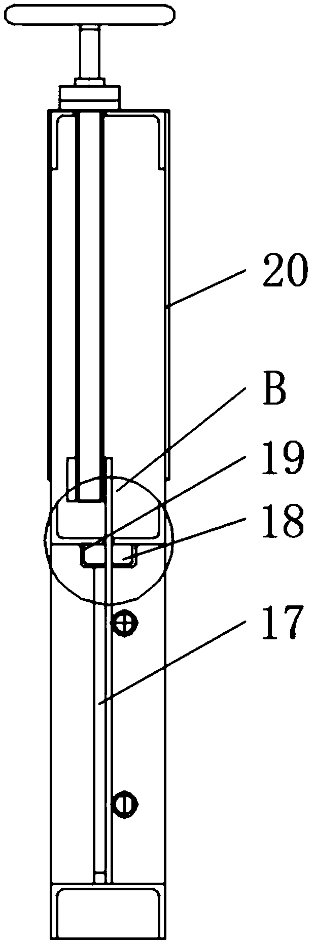
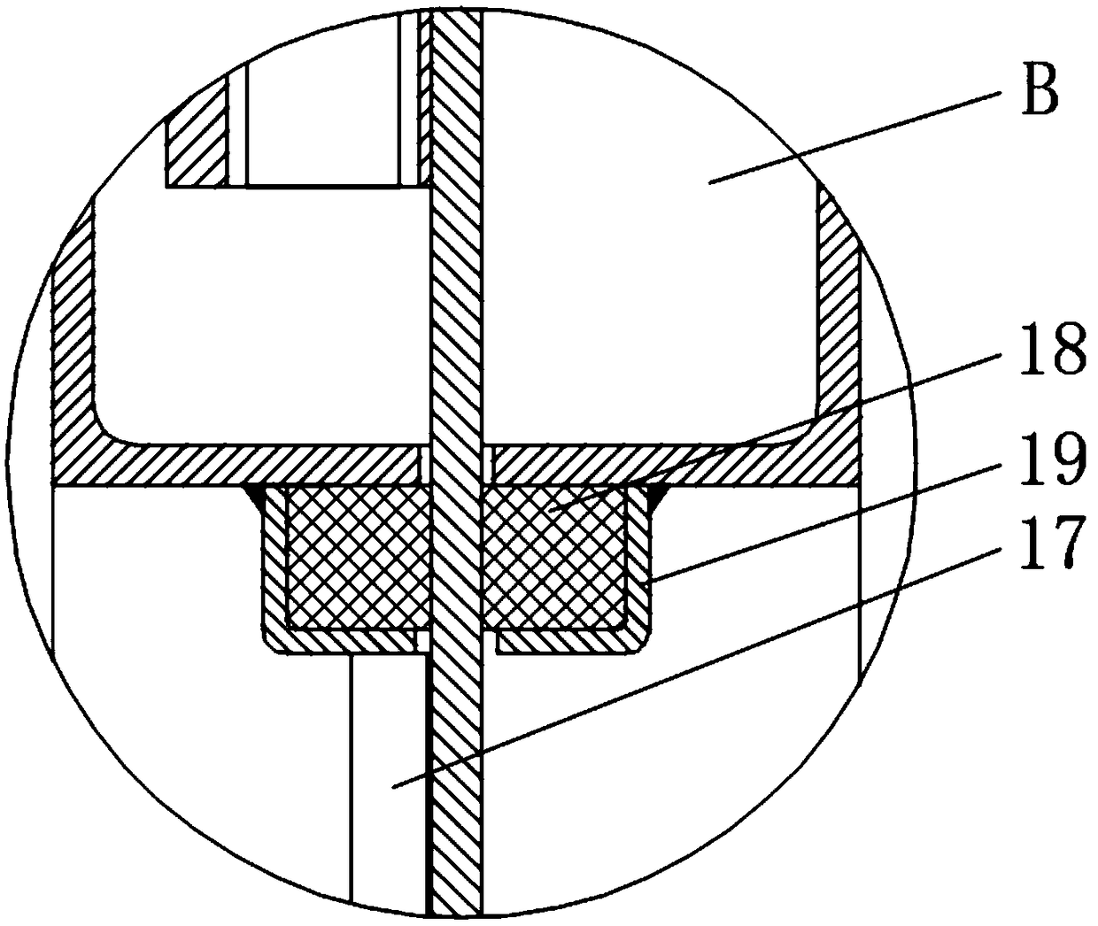
[0021] In order to make the object, technical solution and advantages of the present invention clearer, the following will be combined with specific embodiments and with reference to the appended Figure 5-8 , to further describe the present invention in detail. It should be understood that these descriptions are exemplary only, and are not intended to limit the scope of the present invention. Also, in the following description, descriptions of well-known structures and techniques are omitted to avoid unnecessarily obscuring the concept of the present invention.

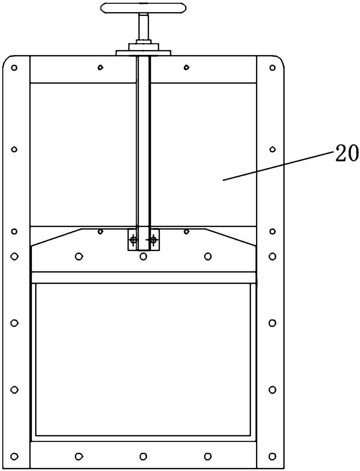
[0022] A manual flapper valve proposed by the present invention, the manual flapper valve includes a valve frame 1;

[0023] Such as Figure 5-8 As shown, a valve frame crossbeam 2 is provided between the front and rear inner walls of the valve frame, and the upper surface of the valve frame crossbeam is provided with a sealing ring positioning sleeve 3, and the position of the sealing ring is limited by the sealin...


PUM


Abstract

The invention discloses a manual gate valve. The manual gate valve comprises a valve frame; a valve frame cross beam is arranged between the front inner side wall and the rear inner side wall of a valve frame; a sealing ring positioning sleeve is arranged on the upper surface of the valve frame cross beam and internally provided with a sealing cavity; sealing rings are symmetrically arranged in the sealing cavity up and down; by the adoption of the sealing mode of the two sealing rings, good leakproofness is ensured; a plurality of adjusting bolts are arranged, it is ensured that pressure of apressing plate on sealing ring pressing pads is even and stable, reliable sealing is ensured, and the pressure of the pressing plate on the sealing ring pressing pads is changed by adjusting the pretightening force of the adjusting bolts; the pressing plate extrudes the sealing ring pressing pads, the sealing ring pressing pads extrude the sealing rings, the deformation amount of the sealing rings is changed, and reliable sealing of a valve plate is ensured; and the structure is compact and reasonable, an upper cover board is omitted, the production cost is reduced, sealing is more reliable,the fault rate is low, the service life is long, maintenance is convenient, the downtime is shortened, and the cost is saved.

Description

technical field [0001] The invention relates to the technical field of gate valves, in particular to a manual gate valve. Background technique [0002] The cement, fly ash, mineral powder and other powdery materials in the concrete mixing plant are usually conveyed from the silo to the weighing bucket by screw conveyors (inclined upward conveying) or pneumatic conveying troughs (inclined downward conveying). The tank is equipped with a manual gate valve at the feed end. Normally, the manual gate valve is open, and the power source of the pneumatic conveying tank is compressed air or a blower. When it is necessary to transport powder into the weighing bucket, the compressed air needs to be activated. Or blower, so there is a certain pressure inside the pneumatic conveying tank, generally 4 ~ 5KPa. Since the pneumatic conveying trough transports the powder obliquely downward, the energy consumed to convey the same weight of material is only 1 / 3 to 1 / 4 of that of the screw con...

Claims


Application Information

Patent Timeline
Patent Type & Authority Applications(China)
IPC IPC(8): F16K3/02F16K3/314F16K3/36F16K27/04
CPCF16K3/0281F16K3/0227F16K3/314F16K3/36F16K27/044
Inventor 吴杰
Owner GUANGDONG KEWEI MASCH EQUIP CO LTD
Why Eureka
Try Eureka