Ammonia method-SCR (Selective Catalytic Reduction) combined desulfurization and denitrification system and method

A technology of desulfurization and denitrification and ammonia desulfurization, applied in the field of sintering pollutant emission reduction, can solve the problems of low cost of sintering flue gas, high cost of denitrification, low efficiency, etc., and achieve the effect of reasonable utilization and low cost joint emission reduction

Pending Publication Date: 2019-02-15
ANHUI UNIVERSITY OF TECHNOLOGY
View PDF2 Cites 0 Cited by
  • Summary
  • Abstract
  • Description
  • Claims
  • Application Information

AI Technical Summary

Problems solved by technology

[0008] The purpose of the present invention is to provide a combined desulfurization and denitrification system based on ammonia method-SCR for the problem of high cost or low efficiency of iron ore sintering flue gas denitrification in the prior art. The annular cooling heat exchanger is installed between the reactors, and the flue gas of the annular cooler is connected to the annular cooling heat exchanger, so that the temperature of the sintering flue gas after ammonia desulfurization is increased, and the sintering flue gas is denitrated at low cost and high efficiency

Method used


Image

  • Ammonia method-SCR (Selective Catalytic Reduction) combined desulfurization and denitrification system and method
  • Ammonia method-SCR (Selective Catalytic Reduction) combined desulfurization and denitrification system and method
  • Ammonia method-SCR (Selective Catalytic Reduction) combined desulfurization and denitrification system and method

Examples


Embodiment 1

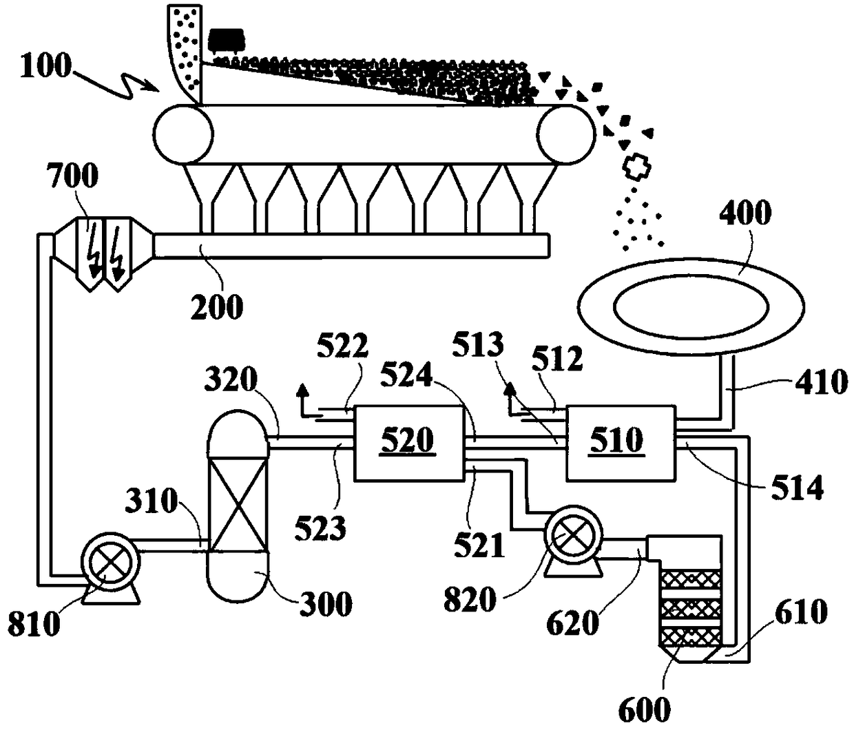
[0039] like figure 1 As shown, an ammonia-SCR combined desulfurization and denitrification system based on this embodiment includes a sintering machine 100, a main flue 200, an ammonia desulfurization tower 300, an annular cooler 400, an annular heat exchanger 510, and a denitrification reactor 600. During the sintering process, the sintering material is sintered on the sintering machine 100 , and the generated sintering flue gas enters the main flue 200 through drafting. The sintered material on the sintering trolley is sintered into sintered ore, and then the sintered ore is crushed by the crushing device and transported to the ring cooler 400 for cooling. The annular cooler 400 is divided into the first annular cooling stage, the second annular cooling stage and the third annular cooling stage along the sinter cooling sequence. The blower at the bottom of the annular cooler 400 cools the sintered ore by blowing air, and the air passes through the sintered ore and takes awa...

Embodiment 2

[0055] In this embodiment, on the basis of Embodiment 1, a tail gas heat exchanger 520 is arranged on the pipeline between the ammonia desulfurization tower 300 and the annular cooling heat exchanger 510, and the denitration outlet 620 of the denitration reactor 600 passes through the pipeline and the tail gas heat exchanger. 520 are connected, and the tail gas passes through the tail gas heat exchanger 520 to exchange heat for the sintering flue gas to raise the temperature.

[0056] The exhaust gas heat exchanger 520 in this embodiment is provided with an exhaust gas heating inlet 521, an exhaust gas heating outlet 522, a first heating inlet 523, and a first heating outlet 524, and the denitrification outlet 620 and the first heating inlet 523 are connected by a pipeline connected, the desulfurized sintering flue gas enters the tail gas heat exchanger 520 from the first heating inlet 523, and the first heating outlet 524 of the tail gas heat exchanger 520 communicates with th...

Embodiment 3

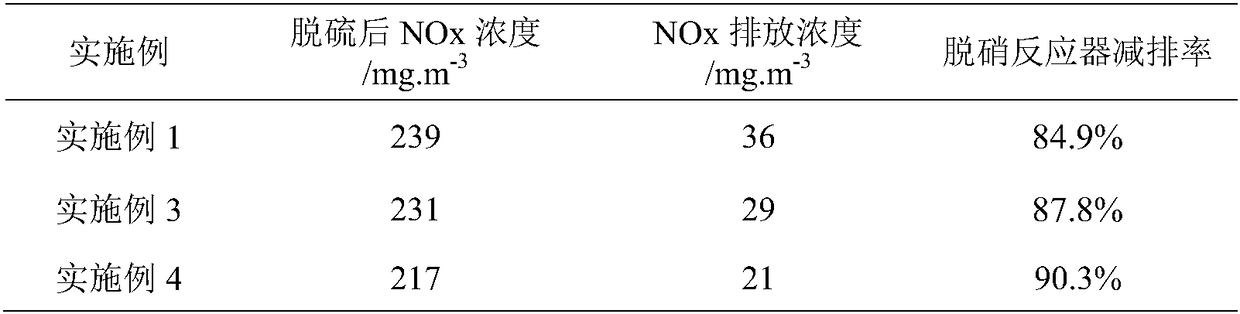
[0065] This embodiment is basically the same as that of Embodiment 1, except that the amount of ammonia sprayed in the ammonia desulfurization tower 300 in this embodiment is 1800m 3 / h, before the sintering flue gas of this embodiment enters the ammonia desulfurization tower 300, the temperature of the flue gas at the desulfurization inlet 310 is 120°C, and the SO 2 The content is 1763mg / Nm 3 , NO x The content is 321mg / Nm 3 ; The sintering flue gas is desulfurized through the ammonia desulfurization tower 300, and the temperature of the sintering flue gas at the desulfurization outlet 320 is 63.5°C, SO 2 The content is 75mg / Nm 3 , NO x The content is 231mg / Nm 3 , the desulfurization rate is 95.7%, and the denitrification rate of ammonia desulfurization tower 300 is 28.0%. And then through the denitrification reactor 600 denitrification, the denitrification outlet 620 NO x Content is 29m 3 / h, the denitration rate of the denitration reactor 600 is 87.8%.


PUM


Abstract

The invention discloses an ammonia method-SCR (Selective Catalytic Reduction) combined desulfurization and denitrification system and an ammonia method-SCR combined desulfurization and denitrificationmethod, and relates to the technical field of sintering pollutant emission reduction. The system comprises a main flue, an ammonia method desulfurizing tower, a ring cooling machine, a ring cooling heat exchanger and a denitrification reactor; the main flue is communicated with the ammonia method desulfurizing tower; the ammonia method desulfurizing tower, the ring cooling heat exchanger and thedenitrification reactor communicate with one another; the flue gas of the ring cooling machine is communicated to the ring cooling heat exchanger; the ring cooling flue gas exchanges heat with the sintering flue gas through the ring cooling heat exchanger and is heated through the ring cooling heat exchanger; the sintering flue gas enters the ammonia method desulfurizing tower for desulfurizing first then exchanges heat and is heated in the ring cooling heat exchanger, and is denitrified in the denitrification reactor. According to the ammonia method-SCR combined desulfurization and denitrification system and the ammonia method-SCR combined desulfurization and denitrification method, the temperature of the sintering flue gas which is subjected to heat exchange can reach the denitrificationreaction temperature required by the denitrification reactor, so that the ammonia method desulfurizing tower and the denitrification reactor can be matched reasonably; therefore, low-cost combinationemission reduction of SO2 and NOx in the sintering flue gas is realized, and meanwhile, effective bleaching of flue gas emission is realized.

Description

technical field [0001] The invention relates to the technical field of emission reduction of sintering pollutants, and more specifically relates to an ammonia method-SCR combined desulfurization and denitrification system and method. Background technique [0002] NOx is one of the main air pollutants at present. In the atmosphere, NOx is easy to form acid rain and photochemical smog, which affects the ecological environment and endangers human health. The status of NOx emissions in the iron and steel industry is particularly severe. According to statistics, the emission of NOx gas in the iron and steel industry accounts for about 10% of the total industrial emission, and the sintering process is one of the main sources of NOx, accounting for about 50% of the total NOx emission. The energy consumption of the iron ore sintering process is mainly the consumption of fossil fuels such as solid fuel coke powder and anthracite coal, accounting for about 75-80% of the total energy c...

Claims


Application Information

Patent Timeline
IPC IPC(8): B01D53/86B01D53/56F23J15/08F23J15/02
CPCB01D53/56B01D53/86B01D53/8628B01D53/8631F23J15/02F23J15/08B01D2251/2062B01D2258/0283
Inventor 春铁军穆固天龙红明朱梦飞余正伟王平孟庆民魏汝飞狄瞻霞李家新秦立浩代梦博
Owner ANHUI UNIVERSITY OF TECHNOLOGY
Why Eureka
Try Eureka