Clinical drainage control device
A technology of a control device and a drainage tube, applied in suction devices, other medical devices, hypodermic injection devices, etc., can solve the problems of endangering the lives of patients, increasing the burden on medical staff and patients' families, and large errors, and improving safety and stability. sex, reduce workload, and ensure the effect of drainage
- Summary
- Abstract
- Description
- Claims
- Application Information
AI Technical Summary
Problems solved by technology
Method used
Image
Examples
Embodiment 1
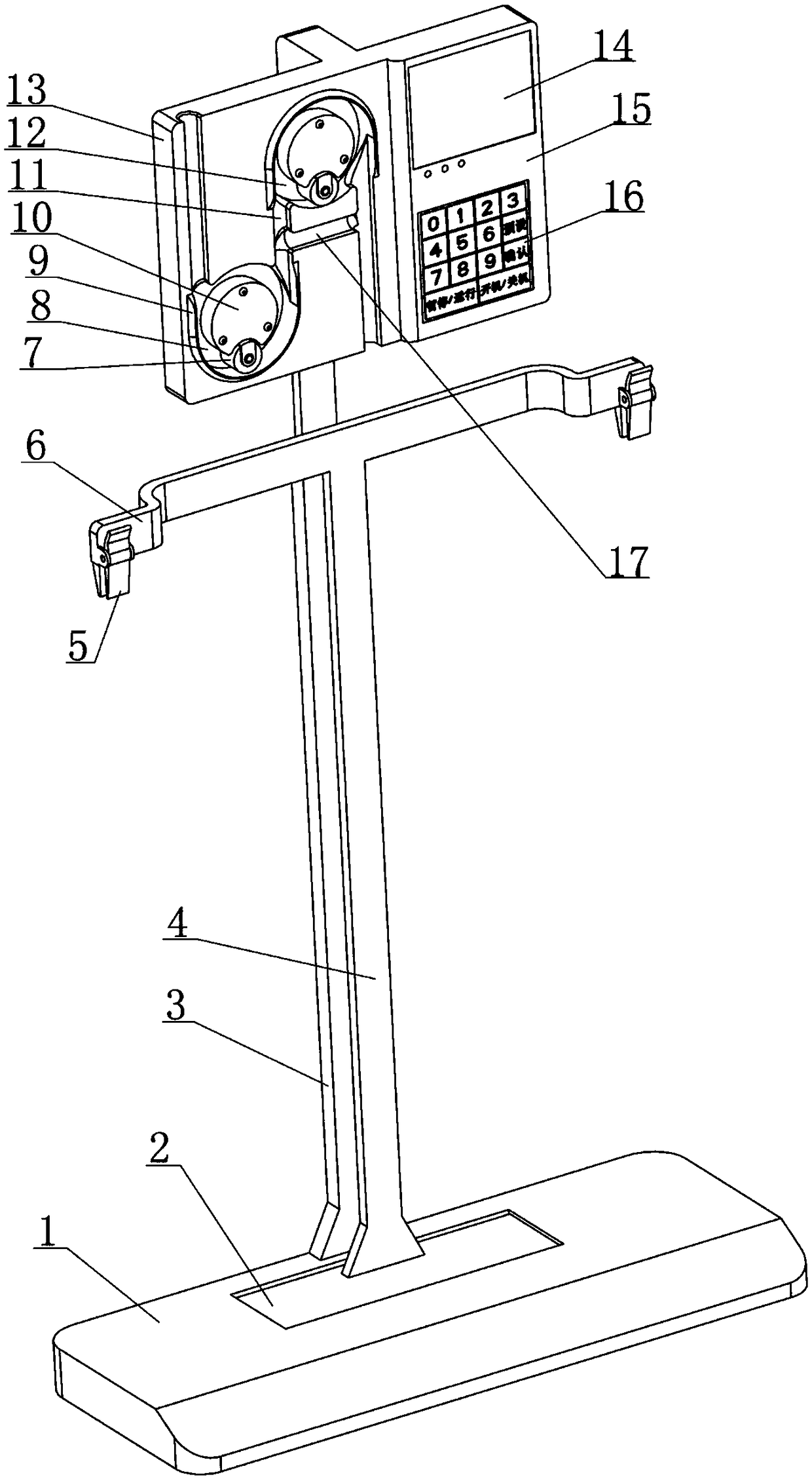
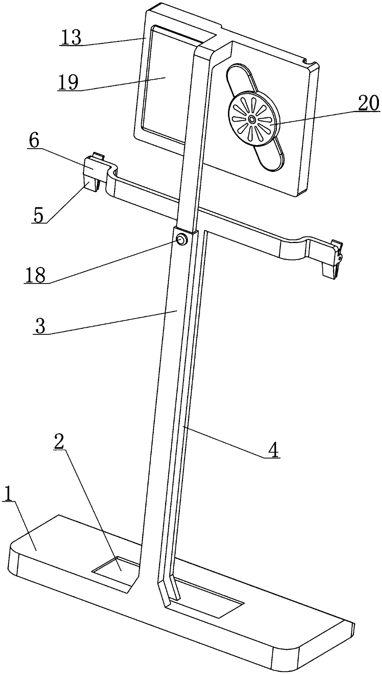
[0044] see figure 1 , 2 As shown, a clinical drainage control device disclosed in this embodiment is composed of a weighing base assembly, a suspension assembly, a drainage adjustment assembly, a controller 15 and a power supply assembly 19;
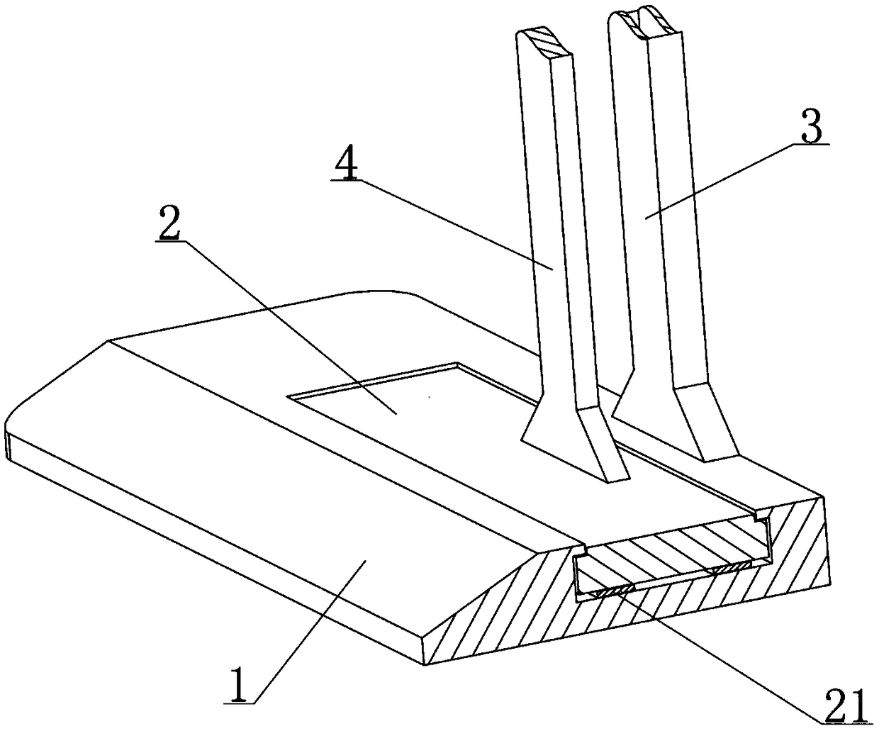
[0045] Among them, see figure 1 , 3 , 9, the weight-based base assembly is composed of a weighing platform 2, a load cell 21 and a base 1 that are sequentially matched up and down, and the load cell 21 outputs a weighing that can reflect the weight of the object above the weighing platform 2. Signal; on the one hand, the weight-based base component is used to provide basic support for the suspension component, the drainage adjustment component, the controller 15 and the power supply component 19, and on the other hand, it is used to feed back the weight signal to the controller 15;
[0046] Among them, see figure 1 , 9 , 10, the suspension assembly includes a vertical rod 4 and a suspension beam 6; the vertical rod 4 is in a vertica...
Embodiment 2
[0073] see Figure 6 , 7 As shown, in the clinical drainage control device disclosed in Embodiment 1, during the forward revolution of the roll 7, after entering the arc-shaped gap 8 each time, it can always move by rolling the drainage tube 22 through rotation, driving the drainage tube 22 to move. The fluid flows backwards to complete a fluid output; during this process, the pressure applied by the roller 7 to the drainage tube 22 should be appropriate. Effusion output efficiency, while the other side needs to prevent the roll 7 from causing excessive pressure on the drainage tube 22, avoiding the damage of the drainage tube 22 located in the arc gap 8, in order to ensure that the above two effects are balanced, the present embodiment is for the roll 7 has a further improvement in the way of cooperation with the orbital wheel 10, and the specific implementation structure is:
[0074] Such as Figure 12 As shown, the roll 7 is fixed in the roll fork 28 through the rotating...
Embodiment 3
[0077] see figure 1 , 3 , 9, in the clinical drainage control device disclosed in Embodiment 1, the controller 15 can obtain the weighing signal continuously fed back by the load cell 21 in real time. Data transmission requirements, this embodiment will obviously increase the overall manufacturing cost of the clinical drainage control device, and also reduce the working stability of the clinical drainage control device, it can be seen that the load cell 21 and the controller 15 are set for transmission The line of data is the best choice to ensure stability and economy, and in the same way, the operating current of the load cell 21 is provided by the power supply assembly 19 through wires and is also the best choice to ensure stability and economy; but there is The problem is that the controller 15 and the power supply assembly 19 are located on the installation board 13, and the two are distributed up and down with the load cell 21. In addition, the controller 15 and the pow...
PUM
 Abstract
Description
Claims
Application Information
 - R&D
- Intellectual Property
- Life Sciences
- Materials
- Tech Scout
- Unparalleled Data Quality
- Higher Quality Content
- 60% Fewer Hallucinations
Browse by: Latest US Patents, China's latest patents, Technical Efficacy Thesaurus, Application Domain, Technology Topic, Popular Technical Reports.
© 2025 PatSnap. All rights reserved.Legal|Privacy policy|Modern Slavery Act Transparency Statement|Sitemap|About US| Contact US: help@patsnap.com


