a tooth extractor
A tooth and shell technology, applied in the direction of dentist pliers, etc., can solve the problem that the hammer takes up a lot of space, and achieve the effect of improving work efficiency and compact overall structure
- Summary
- Abstract
- Description
- Claims
- Application Information
AI Technical Summary
Problems solved by technology
Method used
Image

Examples
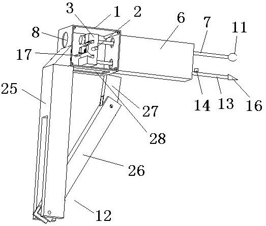
Embodiment 2
[0032] A tooth extractor embodiment 2 is different from embodiment 1 in that the guide mechanism 6 is also pierced with a second slide bar 13, and the second slide bar is provided with a first stop for preventing the second slide bar from continuing to move to the left relative to the hammer. Second block 14, the left end of the second slide bar is provided with a second stop surface 15 for contacting the right side of the hammer, the second stop surface 15 is the left end face of the second slide bar, the right end of the second slide bar The crown splitting head 16 that is used to split the crown of the teeth is connected, and the left end of the second slide bar penetrates from the right end of the guide mechanism 6 and stops in front of the right side of the hammer 3 . In actual use, the first slide bar and the second slide bar of the present invention are not used at the same time. If the patient needs to split the crown of the tooth before tooth extraction, only the secon...
Embodiment 3
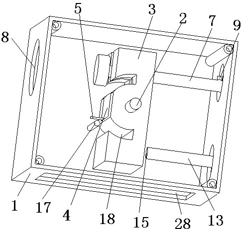
[0033] A tooth extractor embodiment 3 is different from embodiments 1 and 2 in that the housing 1 is provided with a spring foot and a striker for blocking the torsion spring before the hammer hits the first contact surface or the second contact surface. The bump 17 that the hammer contacts, the hammer is provided with an arc-shaped groove 18 for avoiding the bump when the hammer rotates, and the arc-shaped groove 18 can increase the rotation angle of the hammer. By arranging the protrusion 17, it is possible to make the driving hammer 3 of the first torsion spring 5 wind around the first torsion spring 5 before the hammer hits the first contact surface 10 of the first slide bar or the second contact surface 15 of the second slide bar. The spring foot of the rotating shaft 2 stops exerting force on the hammer 3. At this time, the hammer 3 continues to rotate around the rotating shaft 2 by inertia and hits the first contact surface 10 or the second contact surface 15. Therefore,...
Embodiment 4
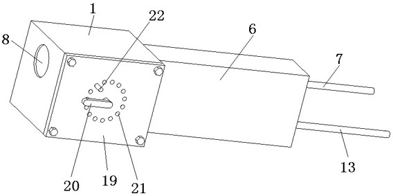
[0034] A tooth extractor embodiment 4 is different from embodiments 1, 2, and 3 in that the rotating shaft can rotate relative to the housing, and the housing is provided with a cover plate 19, and the rotating shaft passes through the cover plate and a support is provided at one end of the cover plate. The arm 20 and the cover plate are provided with at least one limit hole 21 around the rotation axis, and the position of the support arm is fixed by penetrating a limit pin 22 in the limit hole. That is to say, the present invention can drive the rotating shaft 2 to rotate by rotating 20, and the rotating shaft 2 can then twist the first torsion spring 5 to adjust the force of the first torsion spring 5 on the hammer. After the support arm 20 is rotated to the target position, the limit pin 22 is inserted into the limit hole 21 at the position of the support arm 20 to fix the position of the support arm 20. If it is necessary to change the force of the first torsion spring 5 on...
PUM
 Abstract
Description
Claims
Application Information
 - Generate Ideas
- Intellectual Property
- Life Sciences
- Materials
- Tech Scout
- Unparalleled Data Quality
- Higher Quality Content
- 60% Fewer Hallucinations
Browse by: Latest US Patents, China's latest patents, Technical Efficacy Thesaurus, Application Domain, Technology Topic, Popular Technical Reports.
© 2025 PatSnap. All rights reserved.Legal|Privacy policy|Modern Slavery Act Transparency Statement|Sitemap|About US| Contact US: help@patsnap.com