Single-power-source hydraulic auxiliary synchronous lifting table

A technology of synchronous lifting and single power source, which is applied to tables, legs of general furniture, and tables with variable table heights, etc. It can solve the problems of difficult synchronization of lifting legs, high manufacturing cost, and complex structure, and achieves compact structure and easy use. The effect of long life and reliable transmission

Pending Publication Date: 2019-02-15
乔彬
View PDF0 Cites 1 Cited by
  • Summary
  • Abstract
  • Description
  • Claims
  • Application Information

AI Technical Summary

Problems solved by technology

[0003] The purpose of the present invention is to design a simple structure, synchronous Convenient single power source hydraulic auxiliary synchronous lifting table based on hydraulic principle

Method used


Image

  • Single-power-source hydraulic auxiliary synchronous lifting table
  • Single-power-source hydraulic auxiliary synchronous lifting table
  • Single-power-source hydraulic auxiliary synchronous lifting table

Examples


Embodiment 1

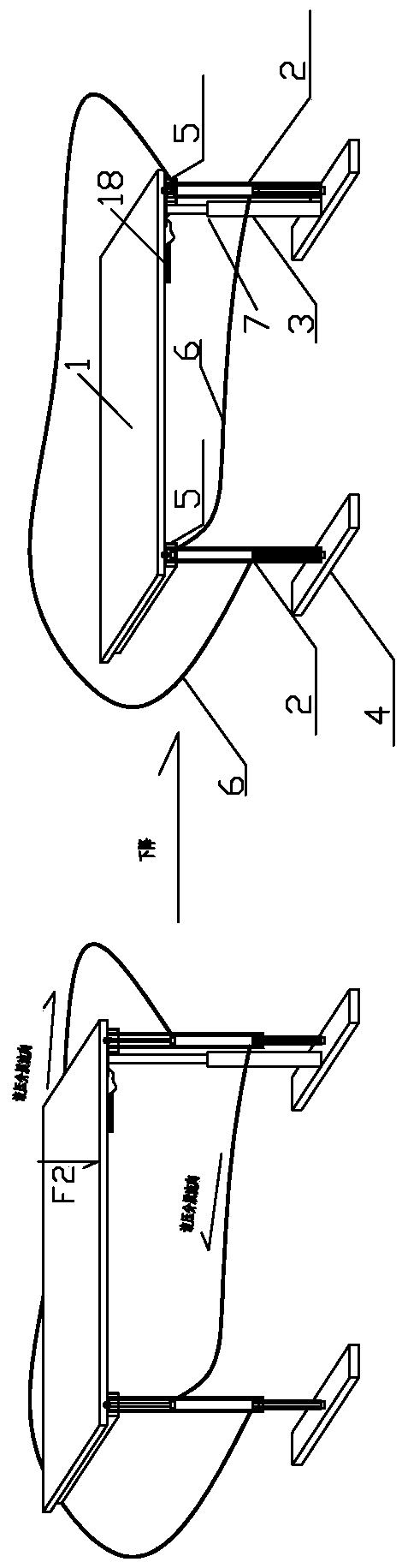
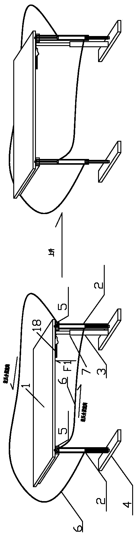
[0058] Such as figure 1 , 2 , 9-12 shown.

[0059] A single power source hydraulic auxiliary synchronous lift table, which includes a desktop 1, two hydraulically driven lifting legs 2, and a pneumatic (hydraulic) dynamic telescopic rod or pneumatic (mechanical) tension and compression spring mechanism 7 as a driving lifting leg 2 follow-up power source legs 3 and base 4, such as figure 1 , 2 As shown, the lifting leg 2 is composed of a hydraulic cylinder and a piston rod. The rod chamber of the first hydraulic cylinder communicates with the rodless chamber of the second hydraulic cylinder through a flexible hydraulic tube 6, and the rod chamber of the second hydraulic cylinder The rod chamber communicates with the rodless chamber of the first hydraulic cylinder through the flexible hydraulic tube 6; when the power source leg 3 rises ( figure 2 ) or drop ( figure 1 ) drives the desktop 1 to rise or fall, and the rise or fall of the desktop 1 drives the piston rods of eac...

Embodiment 2

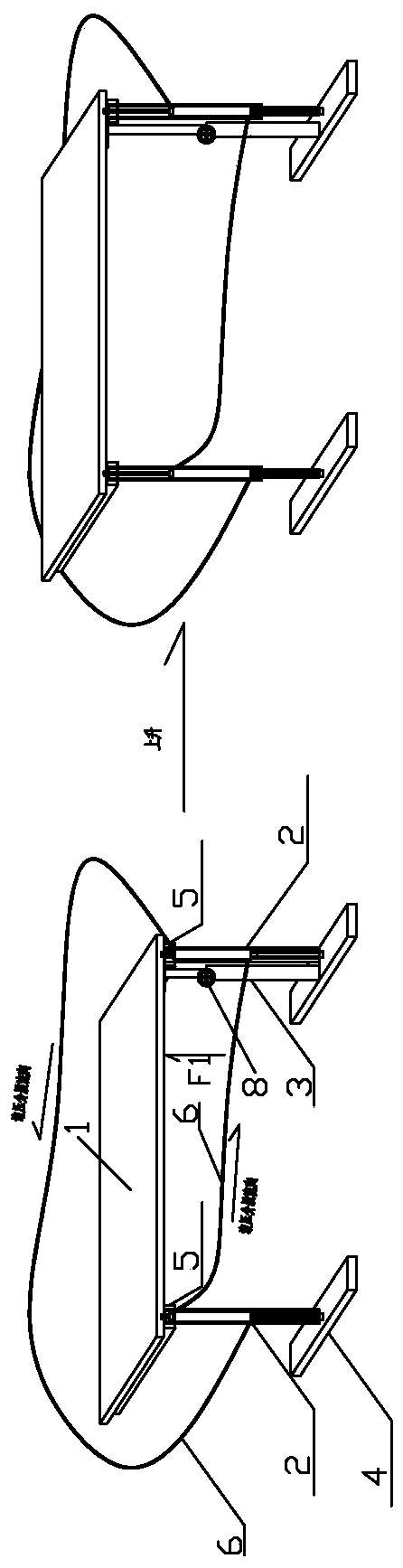
[0065] Such as image 3 , 4 shown.

[0066] The difference between this embodiment and Embodiment 1 is that as the power source leg 3 that drives the lifting leg 2 to go up and down, a separate hand crank lifting mechanism, a foot pedal lifting mechanism or a human mechanical power transmission mechanism 8, a hand rocker lifting mechanism, Pedal elevating mechanism or manpower mechanical force transmission mechanism 8 can adopt the same structure as adopting on the existing lifting table. The rest are all the same as in Example 1.

Embodiment 3

[0068] Such as Figure 5-6 shown.

[0069] The difference between this embodiment and Embodiment 1 is that as the power source leg 3 that drives the lifting leg 2 to lift, it adopts a separate motor lifting mechanism or a motor force transmission mechanism 9, and the motor lifting mechanism or motor force transmission mechanism 9 is the same as the existing lifting table. The structure adopted above is identical, all adopts motor 10 as power source. The rest are all the same as in Example 1.


PUM


Abstract

A single-power-source hydraulic auxiliary synchronous lifting table is characterized by comprising a table top (1), at least two hydraulic-driven lifting legs (2) and a power source leg (3) used for driving the lifting legs to follow up; each lifting leg (2) is composed of a hydraulic cylinder and a piston rod, a rod cavity of the first hydraulic cylinder is communicated with a rodless cavity of the second hydraulic cylinder, a rod cavity of the second hydraulic cylinder is communicated with a rodless cavity of the third hydraulic cylinder, a rod cavity of the third hydraulic cylinder is communicated with a rodless cavity of the fourth hydraulic cylinder, in the same way, a rod cavity of the last hydraulic cylinder is communicated with a rodless cavity of the first hydraulic cylinder. Whenthe power source leg ascends or descends, the table top (1) is driven to ascend or descend; the table top (1) ascends or descends to drive the piston rods of the hydraulic cylinders to extend or contract, so that the lifting legs (2) synchronously ascend or descend. The lifting table is simple in structure, low in cost, convenient to manufacture and good in multi-table-leg synchronous lifting performance.

Description

technical field [0001] The present invention relates to a kind of furniture, especially a desk that can be raised and lowered, specifically a single power source hydraulic auxiliary synchronous lift desk. Background technique [0002] People use various desks when they are working and studying. It is easy to cause cervical spine, lumbar spondylosis and other diseases when using ordinary traditional desks for a long time to sit and work and study. Properly changing the posture of standing and using desks can effectively prevent cervical spine. Spondylosis, lumbar disease, etc. Scientific research shows that the harm of sitting for a long time is even greater than the harm caused by smoking, and insisting on standing for a long time can consume a certain amount of extra calories, maintain body shape and weight, and help the overall health of the body. In order to suit users of different body heights, the existing lifting desks have been designed with various manual, double or ...

Claims


Application Information

Patent Timeline
Patent Type & Authority Applications(China)
IPC IPC(8): A47B9/10A47B13/02
CPCA47B9/10A47B13/02A47B2200/005A47B2200/0056
Inventor 乔彬
Owner 乔彬
Why Eureka
Try Eureka